How Skew Affects Differential Signals
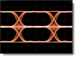
An eye diagram of a differential signal in which there is skew between the two contributing channel signals can result in three "logic" levels as shown in the following pictures. After the two signals have been deskewed, a traditional eye diagram will be displayed that shows two logic levels.
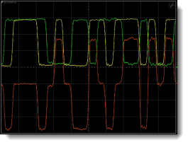
Differential Signal With Skew
Eye Diagram of Signal With Skew
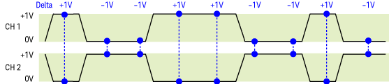
The following drawings show the logic levels before and after an Auto Deskew on two skewed input signals. The differential signal is Channel 1 minus Channel 2. Notice in the top picture that there are three "logic" levels: -1V, 0V, and +1V.
Logic Levels Detected Before Auto Deskew
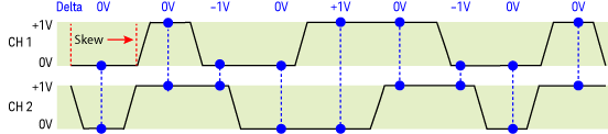
Logic Levels Detected After Auto Deskew