General Thresholds
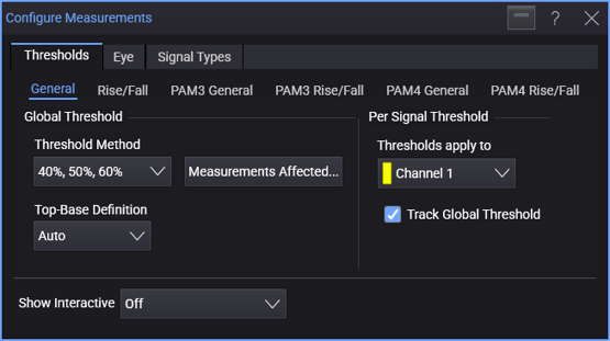
In the General subtab, you can:
- Specify the global threshold (and top-base) definitions.
- Specify unique threshold (and top-base) definitions for each signal.
For each signal:
-
Select the signal under Thresholds apply to.
For a real-time eye made from another waveform in the system, select the original waveform. For a real-time eye in a color grade memory, select the color grade memory.
-
Select Track Global Threshold to use the global threshold (and top-base) definitions for the selected signal.
Or, clear the Track Global Threshold selection to specify unique threshold (and top-base) definitions for the selected signal. Another set of threshold (and top-base) definition controls become available.
When specifying unique threshold definitions for a selected signal, you can click Copy From... to copy the threshold definitions that another signal uses. If the other signal is tracking the global threshold, the selected signal will then switch to tracking the global threshold too.
When you select the ± Hysteresis threshold definition for the selected signal, you can select:
-
Auto to automatically set the Center Threshold to be halfway between Vmin and Vmax and the Hysteresis value to be ±0.05(Vmax - Vmin).
-
Snap to 0 to move thresholds within ±10 mV to zero. This feature is useful for differential signals.
-
Threshold Definitions
The 10% , 50% , 90% selection is often used for single-valued waveforms. The percentage level is based on the measured or user-defined values for Vtop and Vbase.
The types of threshold definitions are:
-
10%, 50%, 90% for typical waveforms (standard IEEE definition).
-
20%, 50%, 80% for waveforms with excessive ringing or overshoot (often used for eye diagrams, also a standard IEEE definition).
-
40%, 50%, 60% for high-speed applications, or any signal with a lot of loss, edges can be missed with the 10%, 50%, 90% or 20%, 50%, 80% definitions. In this case, a tighter range of thresholds still defined as percents of Vtop and Vbase work best. (The ± Hysteresis definition can also specify a tighter range of thresholds, but its middle level is a fixed value.)
-
Custom Percent (%) is similar to the standard IEEE threshold definitions except you define the lower, middle, and upper percentages.
-
± Hysteresis is where you set the middle voltage level (in terms of volts, not percentage) and a hysteresis value. The upper limit for the measurement is the middle voltage value plus the hysteresis value. The lower limit for the measurement is the middle voltage value minus the hysteresis value. Use the ± Hysteresis definition when having the most accurate edge crossing locations is important, for example, when measuring jitter.
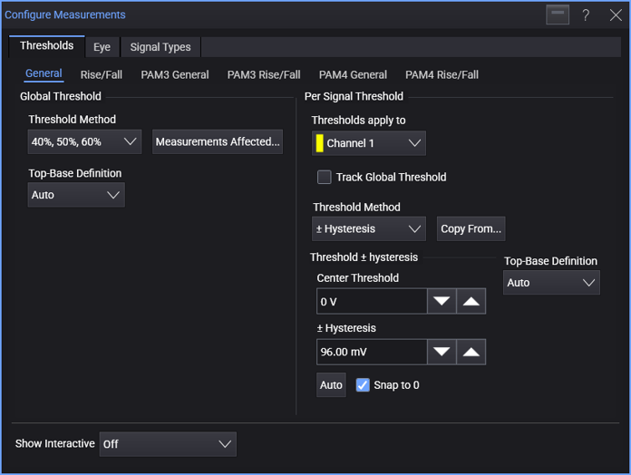
Click Auto to automatically set the Middle Level to be halfway between Vmin and Vmax and the Hysteresis value to be ±0.05(Vmax - Vmin).
When Snap to 0 is enabled, thresholds within ±10 mV are moved to zero. This feature is useful for differential signals.
Use the ± Hysteresis setting when you want to customize the definition in terms of voltages instead of percentages and want the upper and lower thresholds to be symmetric about the middle threshold. (If you do not want symmetry then use the Manual definition.)
For jitter measurements, it is usually best to set the threshold to the 50% level of the source waveform using this custom level +/- hysteresis setting. The hysteresis value should typically be set to about default 5% of the source waveform's amplitude. However, the hysteresis should be increased if the source waveform has inflections on its transitions. The hysteresis may need to be decreased if the vertical eye opening of the source waveform is significantly reduced by excessive ISI or voltage noise.
-
Absolute lets you assign specific amplitudes to the threshold levels. Ensure the thresholds are within the limits of the top-base levels. If the thresholds are outside the top-base boundaries, the measurement results will report which threshold level is in question. You will then have to redefine the threshold levels and repeat the measurement.
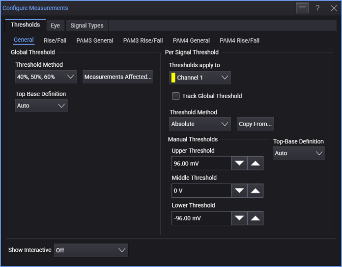
When threshold levels are set to absolute voltages, top-base levels are not used in the fall time calculation.
The Absolute option is not recommended when measuring eye diagrams.
Setting Custom Percent (%) thresholds causes the measurement results table to display the text "* user defined".
Top-Base Definitions (for Percent Thresholds)
Top-Base definition values also affect Mask Test Alignment.
When percent threshold definitions are selected, use the Top-Base Definition control to select:
-
Auto (default) determines the top (100%) and base (0%) levels using histograms of the signal's amplitude.
-
Absolute lets you enter absolute values for the top-base levels. Setting custom thresholds causes the measurement results table to display the text "user defined".
The Absolute option is not recommended when measuring eye diagrams.
Measurements Affected
To see a list of the measurements affected by the threshold and top-base definitions, click Measurements Affected....