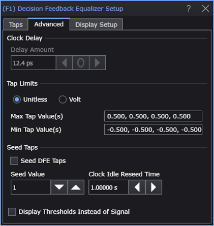
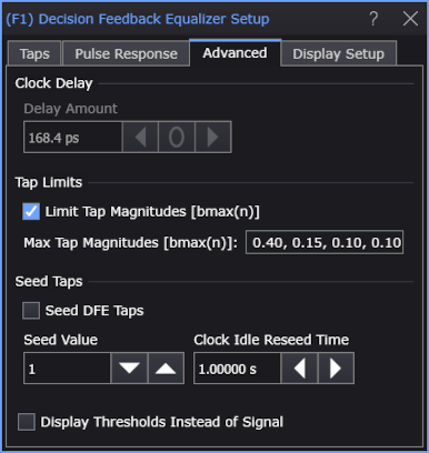
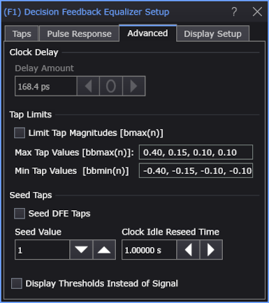
DFE Advanced Tab
The Decision Feedback Equalizer Setup dialog box's Advanced tab lets you enter the Clock Delay and Tap Limits. You can also choose to Display Thresholds Instead of Signal.
| Use Pulse Response Optimization | Limit Tap Magnitudes |
|
|---|---|---|
| Off | On | |
|
|
On (default) |
|
OFF | |
Select:
- Clock Delay — Use this to delay the decision point used by the slicer. The decision point is placed directly between the edges, so the edges are delayed by the same amount. The Clock Delay can be set from −0.5 to +0.5 symbol periods.
-
Tap Limits — Lets you specify the tap limits.
When the Use Pulse Response or Use Pulse Response Optimization setting in the dialog's Taps tab is on and Limit Tap Magnitudes [bmax(n)] is selected (the default setting), the tap limits can be selected as based on maximum tap magnitudes. When Limit Tap Magnitudes [bmax(n)] is not selected, you enter both maximum, bbmax(n), and minimum, bbmin(n) values.
When the Use Pulse Response or Use Pulse Response Optimization setting in the dialog's Taps tab is off, you enter comma-separated Max Tap Value(s) and Min Tap Value(s), and you can select whether you want to enter them as Unitless or Volt values.
-
Seed DFE Taps — Normally DFE will exclude the first several symbols from the real-time eye because they are used to seed the DFE. For example, if you are using a 4-tap DFE, the first four UIs are not included in the real-time eye.
However, if you want to include all of the unit intervals in the real-time eye, you can enable Seed DFE Taps. When Seed DFE Taps is enabled, initial symbols are all seeded to the Seed Value you enter so that the DFE can start working on the first UI.
DFE tap seeding is useful for DDR buses that turn on and off frequently.
When read-write separation is used to generate a real-time eye for DDR read or write bursts, there are bursts of DQS (Strobe) clocks associated with the bursts of read or write data, and then there are intervals with no clocks between bursts. DFE taps need to be reseeded after intervals with no clocks, so there is the Clock Idle Reseed Time field for specifying the time between clocks after which the DFE needs to be reseeded. This value should be slightly less than the smallest time between the end of one burst and the beginning of the next. If you do not want the DFE to be reseeded after intervals with no clocks, you can simply enter a really long "time to exceed".
-
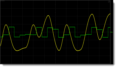
Display Thresholds Instead of Signal — Lets you view the way a hardware DFE works by varying the slicer threshold. The waveform viewed is labeled Operator Threshold Waveform in the Block Diagram of Hardware DFE in this topic.
| DFE Input Waveform | DFE Output Waveform |
|---|---|
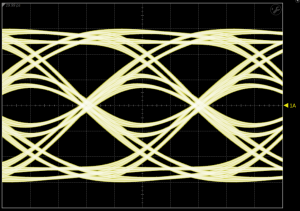
|
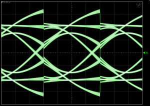
|
Waveform Shown
with "Display Thresholds Instead of Signal" Selected