Interpolation Operator
 The Interpolation operator adds new points between each of the input waveform's points and can be used to reconstruct a band-limited signal. This operator is designed for use on single-valued waveforms and not eye diagrams.
The Interpolation operator requires a single-valued waveform, as opposed to an eye diagram. Be sure that your trigger setup results in a single-valued waveform at the input to this operator.
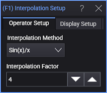
You can select a linear or sin(x)/x Interpolation Method. The sin(x)/x method is the default and is preferred when reconstructing a signal (having evenly spaced samples) that has been bandlimited. The new points are evenly spaced between the original points. The number of points in the output waveform is determined by the Interpolation Factor, which can be set to values of 2, 4, 8, 16, 32, or 64. The relationship between the number of input and output waveform points is shown in the following equation:
- output waveform points = AX − A + 1
where X is the number of input waveform points and A is the interpolation factor.
As an example, specifying an interpolation factor of 8 for a 100 sample-point waveform results in a 793 point output waveform:
- output waveform points = 8(100) − 8 + 1 = 793
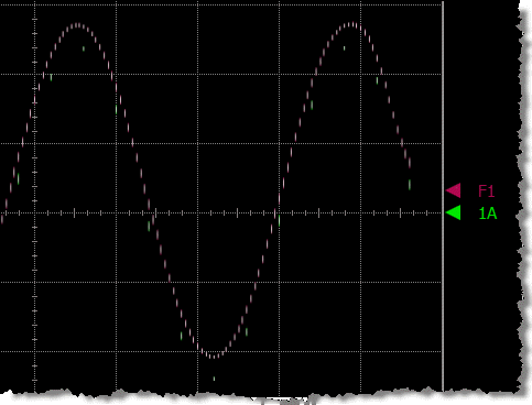
The following figure shows an output waveform constructed using an interpolation factor of 8. The input waveform (1) is shown with 13 sampled green points. The red points show the output waveform (F1).
Display Setup
Each operator's setup includes a Setup section that has the selections that are shown in the following generic setup dialog box. Use these settings to control the display of the operator's output waveform, including turning the display on or off. Use the Name field to display an identifying name to the waveform which can be helpful for screen captures or when multiple waveforms are displayed. The settings also include the output waveform's color, scaling, and signal type. The scaling Automatic selection allows the output waveform to track changes to the scaling of the input waveform. This is the setting that you would normally want to use.
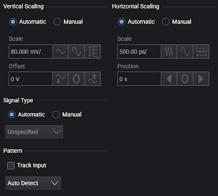
The signal Pattern can be used for BER (Bit Error Ratio), SNDR (Signal to Noise and Distortion Ratio), and other measurements. You can specify the math function has the same pattern as the input waveform (Track Input), Auto Detect the pattern, choose a Known Pattern from a list, or specify your own pattern using a Pattern File.