Oscilloscope Back Panel
Click on the picture!
Figure. Back-Panel View

Power Cord Receptacle
| Connector | Notes |
|---|---|
| Power cord |
Attach the supplied power cord here. The symbol above the power cord connector is a caution to use the power cord that came with the oscilloscope. |
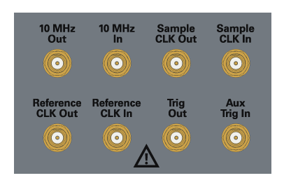
Clock and Trigger Inputs and Outputs
| Connector | Notes |
|---|---|
| 10 MHz Out | You can use the 10 MHz Out BNC connector to send the oscilloscope’s 10 MHz reference clock output signal to another instrument’s reference clock input. |
| 10 MHz In |
The 10 MHz In BNC connector is used to phase lock the oscilloscope to an external timebase reference clock. This input can also be used to provide a lower phase noise reference than the internal reference so that the oscilloscope’s jitter measurement floor is lowered on long (≥10 ms) acquisitions. If the external timebase reference clock frequency and amplitude do not meet certain requirements (see Input and Output Ratings), the internal reference will be used and a message will appear. To use the external timebase reference clock, connect it to the 10 MHz In BNC connector. Then, in the Infiniium oscilloscope application’s Timebase tab (select the colored portion of the Horizontal badge), enable the 10 MHz External Reference Clock. |
| Sample CLK Out, Sample CLK In |
These connectors are used for MultiScope applications and should remain disconnected during single-oscilloscope applications. A 50 Ω termination has been included on the Sample CLK Out connector. Do not operate the instrument with this output unterminated. Operating the instrument with this output unterminated will damage the instrument and void the warranty. |
| Reference CLK Out, Reference CLK In |
These connectors are used for MultiScope applications and should remain disconnected during single-oscilloscope applications. |
| Trig Out | Pulses corresponding to oscilloscope triggers can be sent to the Trig Out SMA output. |
| Aux Trig In | You can set up the oscilloscope to trigger on the auxiliary trigger signal connected to the Aux Trig In SMA input. |
Motherboard I/O Panel Connectors

| Connector | Notes |
|---|---|
| External monitor | This VGA connector is for a legacy external monitor. |
| USB 3.0 device port | This port is for connecting the oscilloscope to a host PC. You can then issue remote commands from a host PC to the oscilloscope. |
| DisplayPort port | This display port is for driving an external monitor. |
| LAN | This connector is compatible with 10/100/1000Base T protocols. |
| USB host ports | These ports are for connecting USB mass storage devices or printers to the oscilloscope. CAUTION: Do not connect a host computer to the oscilloscope’s USB host port. A host computer sees the oscilloscope as a device, so connect the host computer to the oscilloscope’s device port. |
| Audio | The audio connectors (for line-in, front speaker out, and microphone input) are functional on older units but not on newer units. When the audio connectors are not functional, the motherboard I/O label has “disabled audio function” symbols, and the audio ports are capped. |