Aliased Jitter Spectrum
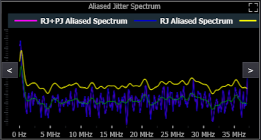
The Jitter analysis software uses a spectral method of separating RJ from PJ. You can view the internal RJ+PJ power spectrum as well as the separation threshold used to separate the RJ from PJ as shown in the screen shot above.
As shown above, the plot displays four traces: the original RJ+PJ spectrum (pink), the remaining RJ spectrum after the PJ has been removed (blue), the decision threshold used to separate the PJ frequency components from the RJ components (yellow), and the RJ baseline (green).
In Periodic mode (see Pattern Sequence), each PJ component affects only a single frequency point. So, when it is removed, none of the other frequency points are affected. In arbitrary mode, however, each PJ component may affect multiple frequency points. In fact, in some cases, each PJ component will affect all of the other frequency points.
When the Pattern Sequence is set to Arbitrary, the Jitter analysis software always uses the arbitrary method of DDJ separation and the arbitrary method of RJ/PJ separation. When the Pattern Length is set to Periodic, however, the Jitter analysis software uses the periodic method of DDJ separation, but it only uses the periodic method of RJ/PJ separation if the memory depth if large enough to capture 1024 whole patterns in each acquisition. Otherwise, it resorts to the arbitrary method of RJ/PJ separation. To remind you which method is being used, it is listed in the title of the graph (the screen shot above shows that Periodic is listed).
The Jitter analysis software uses a non-linear decision threshold that can follow the non-flat baseline of RJ. This non-linear threshold is only used in narrow RJ Bandwidth mode because the wide RJ bandwidth mode tells the Jitter analysis software that you already know that the RJ baseline is flat with frequency.