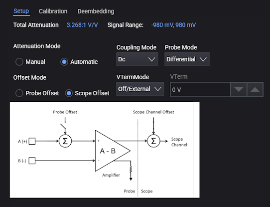
Setup
In the Setup tab on the lower right portion of the Probes/External Hardware Setup dialog box, you have these types of probe information and controls:
-
Total Attenuation — Shows the total attenuation of the probing hardware including all external scaling, probes, and accessories. See Attenuation and Vertical Scale.
-
Signal Range — Displays the actual available range of the probing hardware. The value is based on total channel gain, channel scale and offset, the probe state, and the probe offset mode.
The signal range is also shown as a bar on the right side of the waveform grid.
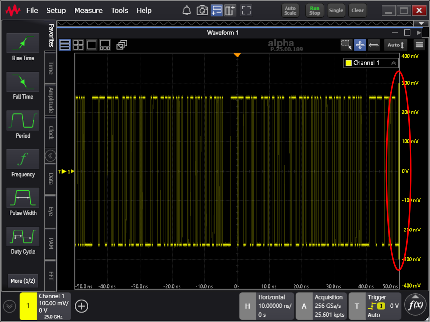
Signal range behaves differently depending on whether probe offset or oscilloscope offset is used. When oscilloscope offset is used, the signal range is always centered around 0 V. Because oscilloscope offset is applied after the probe's amplifier, it cannot actually change the signal range. However, when probe offset is used, the signal range is centered around the probe's offset because the offset is applied before the probe's amplifier. So, to actually shift the signal range of the probe, you must use probe's offset. When probe offset is used, and no signal is attached, the oscilloscope measures the probe's offset as a signal. This is correct behavior and is verified by the signal range bar.
-
Attenuation Mode — If set to Manual, you can use the Attenuation/Gain/Gain (dB) field to enter the value; otherwise, the value is automatically calculated and displayed.
-
Offset Mode — Some probes let you specify whether offset is adjusted in the probe or the oscilloscope. See Vertical Offset.
-
Coupling Mode — Selects the type of coupling used by the probe, for example: GND, DC, AC, AC_LF1, AC_LF2, AC_LF3, VC, or Off.
Most Keysight probes are DC coupled, but if a probe has the options for different coupling, they will be available here.
Probe coupling mode is independent of any channel input coupling mode.
-
Probe Mode — If a probe lets you select its mode, its options will appear here, for example: Differential, Single Ended A, Single Ended B, or Common Mode.
For most probes, the mode is determined by the physical hardware. All passive probes are single ended. Probes with an active differential amplifier are differential. For these probes, the mode is shown and cannot be changed.
If a multimode probe is attached, not all modes may be available. The selection can be limited by the head attached and how the probe is connected to your circuit. Multimode probes often require a grounding connection to your circuit. Each mode has different attenuations and offsets that are applied to the signal. This mode selection will also change whether oscilloscope offset, probe offset, or both are allowed.
-
VTermMode — Available when a probe has the ability to select the voltage termination mode, this control lets you select: Off/External or Internal.
Some technologies such as HDMI require a non-ground termination voltage, and it is best to measure those signals with a probe that is also terminated with the same voltage. This is called voltage termination mode or V-Term mode.
In some cases, as with differential SMA probe heads that have a V-Term input, the V-Term input can be physically grounded with a shunt, left floating, or connected to the DUT's termination voltage, and there is no need for software control.
However, some probes let you control the V-Term voltage internally, and the VTermMode control is necessary.
-
VTerm — When the Internal voltage termination mode is selected, this field lets you enter the internal voltage termination value.