Timebase Controls
Use the Horizontal badge and the Timebase tab of the Infiniium Scope Setup dialog box to specify the (fixed) horizontal reference location, to specify the delay of the reference location with respect to the trigger (t=0), and to adjust the horizontal scale.
![]()
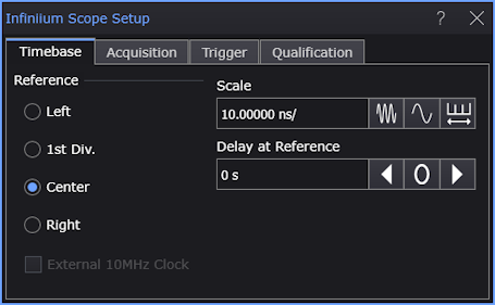
You can place the horizontal Reference at the graticule's left side, 1st division, center, or right side.
The following picture shows the horizontal reference set to Center. The horizontal reference is marked with a hollow triangle at the top of the graticule.
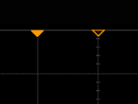
The trigger position (t=0) is marked with a solid triangle. Because "time = 0" is the trigger point, the Reference control lets you specify whether you want to capture data after the trigger, around the trigger, or before the trigger.
Use the Scale field to enter the horizontal time per division. Use the field buttons to increase the scale, decrease the scale, and toggle between coarse and fine scale adjustment.
When you click Auto Scale on the menu bar, Infiniium adjusts the horizontal scale based on the trigger source and input selected. The waveform is evaluated and adjusted so that at least one cycle (or edge) of the waveform is displayed (within 6 horizontal graticule divisions).
The Delay at Reference value is the location of the reference with respect to the trigger. You can adjust the Delay at Reference value to, in essence, move the trigger position about the reference location. When the Delay at Reference value is zero, the trigger position is the same as the horizontal reference location, and the triangle markers are overlaid.
External 10MHz Clock
When Infiniium is connected to an oscilloscope, this control lets you use an external clock for the horizontal timebase system instead of the internal clock.
The oscilloscope has a 10 MHz IN SMA connector that you can use to synchronize (phase lock) the oscilloscope's horizontal timebase system to a reference clock that you provide. This input can also be used to provide a lower phase noise reference than the internal reference so that the oscilloscope's jitter measurement floor is lowered on long (≥10 ms) acquisitions.
The clock you provide must meet the following specifications:
- Input frequency lock range: 10 MHz ±20 ppm
- Amplitude, sine wave input: 630 mVpp (0 dBm) min to 3.54 Vpp (+15 dBm) max
- Amplitude, square wave input: 500 mVpp min to 2.83 Vpp max
- Input impedance: 50 Ω (typical)
Notes:
- The oscilloscope will lock to input amplitudes ranging from -5 dBm to +15 dBm (sine wave); however, the best intrinsic jitter performance is achieved between 0 dBm and +15 dBm.
- For inputs at or slightly below -5 dBm, the oscillator assembly will disconnect from the external reference input, the oscilloscope application will automatically connect to the internal reference signal, and a message will appear indicating the external reference signal amplitude is too low and the oscilloscope is now using the internal reference. To continue using the external reference, you need to increase the input amplitude above -5 dBm so the hardware will remain connected to the external reference signal.
- For inputs at or slightly above +15 dBm, the oscillator assembly will disconnect from the external reference input, the oscilloscope application will automatically connect to the internal reference signal, and a message will appear indicating the external reference signal amplitude is too high and the oscilloscope is now using the internal reference. To continue using the external reference, you need to reduce the input amplitude to +15 dBm or less so the hardware will remain connected to the external reference signal.