Pattern
The Pattern trigger mode triggers on logic level patterns and up to one edge that occur among multiple input channels.
-
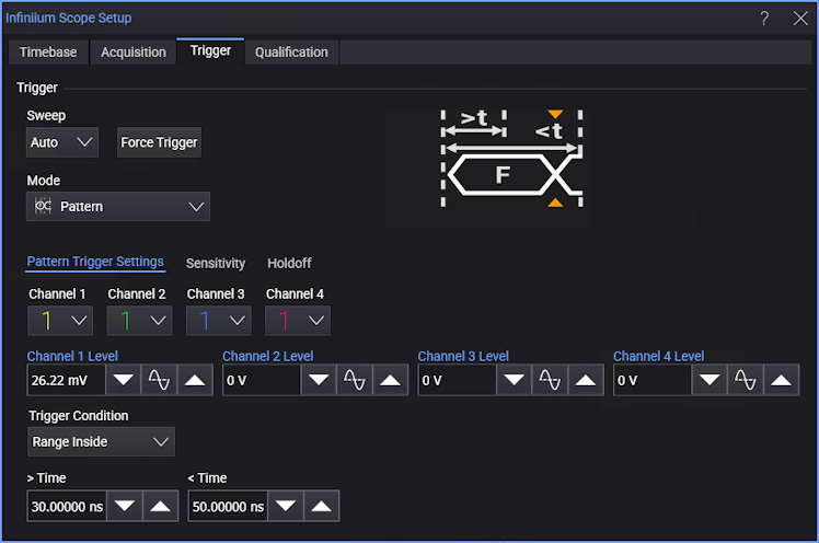
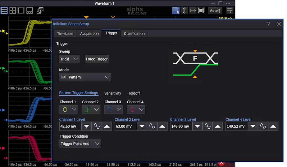
Channel N — For each input channel, select the logic level (1 (high), 0 (low), or X (don't care)) or edge (rising, falling, or either) that should be included in the pattern. The pattern can include an edge identifier on one channel only.
A value is considered a 1 (high) when the waveform's voltage level is greater than its trigger threshold level and a 0 (low) when the voltage level is less than its trigger threshold level.
If a channel is set to X (don't care), it is not used as part of the pattern criteria.
A pattern of all don't cares means no channels are part of the pattern criteria, and therefore, there will be no triggers (unless Auto sweep triggers are enabled).
-
Channel N Level — For each input channel, enter the trigger threshold level in the field or use the increase, 50%, or decrease buttons.
Note that the trigger level indicators in the Waveform content window(s) show "L" (for "level") or "E" (for "edge") depending on the Channel N selections in the pattern trigger setup.
-
Trigger Condition — Selects the time the pattern must be present for in order to cause a trigger.
When the pattern consists of logic levels only, you have these options:
- Entered — Triggers on the edge of the signal that makes the pattern true.
- Exited — Triggers on the edge of the signal that makes the pattern false.
- < Time — Triggers when the pattern is present for less than the specified Time.
- > Time on Exit — When the pattern is present for greater than the specified Time, triggers when the pattern ends (on the signal edge that makes the pattern invalid).
- > Time on Timeout — When the pattern is present for greater than the specified Time, triggers when the time is exceeded.
- Range Inside — Trigger when the pattern is present for a time within the range specified by the > Time and < Time values. The trigger occurs on the signal edge that makes the pattern invalid (like "on Exit").
- Range Outside — Trigger when the pattern is present for a time outside the range specified by the < Time and > Time values.
When the pattern includes an edge identifier, you have these options:
- Trigger Point And — The trigger point is the edge AND the pattern on the remaining channels.
- Trigger point Nand — The trigger point is the edge AND NOT the pattern on the remaining channels.
Edges are identified when a signal passes through the trigger threshold voltage. The direction of the edge is determined based on hysteresis around the trigger threshold.
The combination of an edge and a pattern is known as a State trigger.