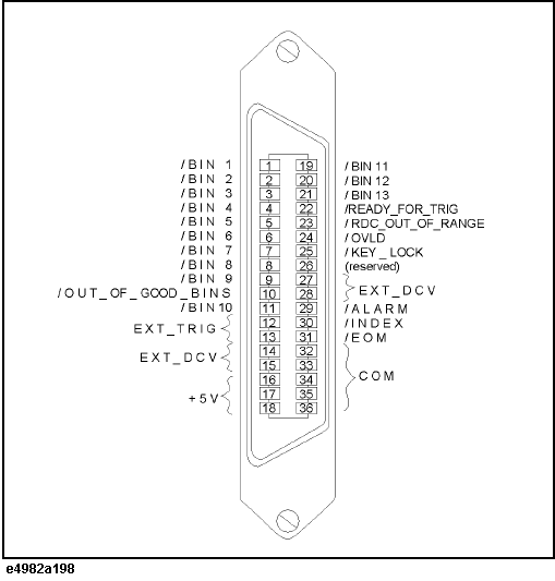
The figure below illustrates the layout of the input/output signal pins on the handler interface connector.
Handler Interface Connector Pin Layout
Description of the Handler Interface Input/Output Signals
|
Pin number |
Signal name |
Input/ Output |
Description |
|
1 |
/BIN1 |
Output |
These signals indicate the result of sorting. When a DUT is sorted into a bin, the corresponding signal (one of pins 1 through 11 and 19 through 21) changes to the Low level for a DUT that does not fall within the Rdc limit or cannot be measured (overload). |
|
2 |
/BIN2 |
||
|
3 |
/BIN3 |
||
|
4 |
/BIN4 |
||
|
5 |
/BIN5 |
||
|
6 |
/BIN6 |
||
|
7 |
/BIN7 |
||
|
8 |
/BIN8 |
||
|
9 |
/BIN9 |
||
|
10 |
/OUT_OF_GOOD_BINS |
||
|
11 |
/BIN10 |
||
|
12, 13 |
Input |
An external trigger signal. Available when the trigger mode is set to Ext (external trigger source). The instrument is triggered when the pulse reaches a rising/falling*1 edge. |
|
|
14, 15 |
EXT_DCV |
External DC voltage. Supplies voltage necessary for driving input signals. The pin accepts input voltage within the range from +5 V to +24 V. |
|
|
16, 17, 18 |
+5 V |
Output |
Internal DC voltage. Maximum current is 500 mA. |
|
19 |
/BIN11 |
These signals indicate the result of sorting. For more information, refer to the description of pins 1 through 11. |
|
|
20 |
/BIN12 |
||
|
21 |
/BIN13 |
||
|
22 |
/READY_FOR_TRIG |
The /READY_FOR_TRIG signal changes to the Low level when the instrument can be triggered. When the handler receives this signal, it can input an external trigger signal to the instrument. |
|
|
23 |
/RDC_OUT_OF_RANGE |
The /RDC_OUT_OF_RANGE signal changes to the Low level when the result of Rdc measurement does not fall within the specified limit range. |
|
|
24 |
/OVLD |
The /OVLD signal changes to the Low level when analog measurement cannot be performed (overload). |
|
|
25 |
/KEY_LOCK |
Input |
Key lock signal. Changing this signal to the Low level locks the E4982A's front panel (keys and rotary knobs), keyboard and mouse. |
|
26 |
(Reserved). |
- |
Currently not in use. Leave this pin unconnected. |
|
27, 28 |
EXT_DCT |
Input |
External DC voltage. For more information, refer to the description of pins 14 and 15. |
|
29 |
/ALARM |
Output |
The /ALARM signal changes to the Low level when an alarm condition is detected; for example, when the instrument does not satisfy a self-test item, or a particular circuit malfunction. |
|
30 |
/INDEX |
The /INDEX signal changes to the Low level when analog measurement is complete. When the handler receives the signal, it assumes that it is ready to connect the next DUT. However, no measurement data is available until the /EOM signal is received. |
|
|
31 |
/EOM |
The /EOM signal changes to the Low level when the instrument is ready to return measurement data and sort results after performing one complete cycle of measurement. |
|
|
32, 33, 34, 35, 36 |
COM |
- |
Common for output signal pull-up voltage. |
*1. The :TRIG:SLOP command sets the polarity (rising or falling).
Other topics about Connecting the Instrument to a Handler Interface