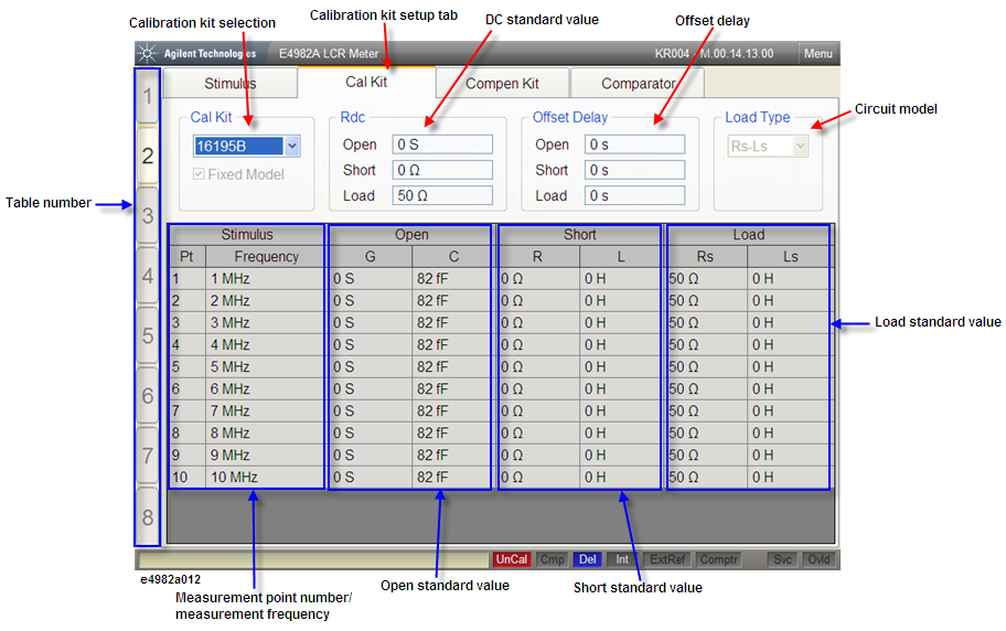
The calibration kit setup display shown in the following figure appears when you press the Stim Table key the required number of times.
When the Cal Kit tab is displayed in front of the other three tabs, the screen shows the calibration kit setup display. If another setup display appears, click this tab or press Stim Table key several times to get the calibration kit setup display.
You can choose either to use the predetermined value for the 7-mm calibration kit (7-mm standard) or user-defined value as the calibration kit definition. To use the Keysight Technologies 16195B 7-mm calibration kit, select 16195B. In case of selecting 16195B, all calibration kit values should have been entered and you are not allowed to change the definition.
If you select User Defined, you are allowed to enter the values for the calibration kit definition. If you select the Fixed Model, enter the definition for measurement point number 1, which is then automatically applied to the other measurement point numbers.
Highlights the active table number. The E4982A has eight tables and each table allows a maximum of 201 measurement points to be set. Use the measurement point setup display to set the measurement point conditions (measurement frequency, averaging factor, oscillator level for the measurement point number) for each table.
Displays the measurement points (measurement point number and measurement frequency) in the selected measurement point table.
Enter the open standard value.
Enter the short standard value.
Enter the load standard value.
Select one of the three circuit models (Rs-Ls, Ls-Q, or Cp-D) for the load parameter.
Depending on the calibration kit used, offset delay may have to be set. In such cases, enter the offset delay values for open standard, short standard, and load standard.
Enter the calibration kit definition for E4982A DC resistance (Rdc) measurement.