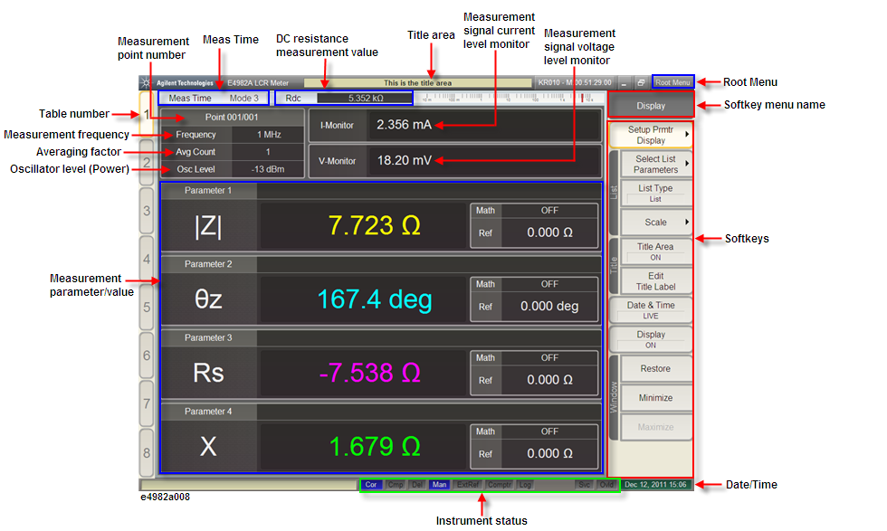
The single point measurement display shown in the following figure appears when you press the Point Meas key.
Enter your preferred title to be displayed in here.
Highlights the active table number. The E4982A has eight tables and each table allows a maximum of 201 measurement points to be set. Use the measurement point setup display to set the measurement point conditions (measurement frequency, averaging factor, oscillator level for the measurement point number) for each table.
Displays the active measurement point number. Use the measurement point setup display to set the measurement point conditions (measurement frequency, averaging factor, oscillator level for the measurement point number) for each table.
Indicates the measurement frequency of the active measurement point. The conditions (measurement frequency of measurement point, averaging factor, oscillator level for the measurement point number) for each table are set in measurement point setup display.
Displays the oscillator level of the active measurement point. Use the measurement point setup display to set the measurement point conditions (measurement frequency, averaging factor, oscillator level for the measurement point number) for each table.
Displays the measurement averaging factor of the active measurement point. Use the measurement point setup display to set the measurement point conditions (measurement frequency, averaging factor, oscillator level for the measurement point number) for each table.
Displays the monitor value of the current level applied to the DUT in the measurement.
Displays the monitor value of the voltage level applied to the DUT in the measurement.
Displays the measurement mode that represents the speed of the measurement. Refer to How to Change Measurement Mode.
When the DC resistance (Rdc) measurement function is turned ON, the measurement result is shown here. The limit for making “pass or fail” judgment can be set for the DC resistance (Rdc) measurement result, and this can be used for checking the contact condition of the measurement electrodes and the DUT in the case of impedance measurement.
Displays the generic softkey menu for a set of the softkeys described in Softkeys.
Displays the grouping name of a collection of softkeys. At the top level, this name often but not necessarily corresponds to the name of the selected hardkeys.
The softkeys are shown here. To operate the softkeys, first press the Stim Table, Meas Setup, Prmtr, Data Export, Display, Trigger Mode, Analysis, Save/Recall or System as described in Key Operation Overview to call up the desired softkey menu. Then select the desired softkey using any of the following methods:
Turn the rotary knob on the front panel clockwise or counterclockwise to vertically move the selection cursor over the softkey label. Then press the rotary knob to select the softkey.
Click the softkey label with the mouse connected to the E4982A.
Press the arrow keys ([h] and [i]) of the keyboard connected to the E4982A to vertically move the selection cursor over the softkey label. Then press the ENTER key to select the softkey.
As the E4982A comes with touch screen LCD, you can select the desired softkey by touching the LCD screen directly with a finger. Do not press the surface of the LCD screen with a sharp object (e.g., a nail, pen, or screwdriver). Pressing the surface with a sharp-pointed object will damage the LCD screen surface or cause the screen to fail.
Displays the current date and time. To change the date and time settings, refer to Change Date/Time Settings.
Displays the status of crucial operating conditions of the E4982A.
|
Display |
Definition |
|
UnCal (red display) Cor (blue display) |
Calibration is not executed. Calibration is executed. |
|
Cmp (blue display) |
Compensation is executed. |
|
Del (blue display) |
Fixture compensation (electrical length and delay time compensation) has been set (a value other than 0 has been set for the electrical length of the fixture). |
|
Int (blue display) |
The trigger mode is internal trigger mode. The E4982A itself executes the trigger continuously. |
|
Man (blue display) |
The trigger mode is manual trigger mode. Trigger is executed when the Trigger key on the front panel is pressed. |
|
Ext (blue display) |
The trigger mode is external trigger mode. Trigger is executed by a signal sent through the external trigger input terminal or the handler interface. When the handler interface external trigger voltage is set from 5 to 15 volt, Ext L (5 to 9 V) or Ext M (9.1 to 15 V) is displayed. |
|
Bus (blue display) |
The trigger mode is bus trigger mode. Trigger is executed via GPIB, USB or LAN. |
|
ExtRef (blue display) |
The external frequency reference signal is input and the E4982A test signal is phase-locked to that reference signal. |
|
Comptr (blue display) |
Comparator (BIN sort) is turned ON. |
|
Log (blue display) |
Displayed when logging is started. To start logging, press Analysis > Start Logging. Refer to Data Logging for Statistical Analysis. |
|
Svc (red display) |
The E4982A is in service mode. The service mode is used for self-diagnosis and repair of the E4982A. This means that you cannot obtain a measurement guaranteed by the specifications. If this indicator is lit during normal use, the instrument may be malfunctioning. |
|
Ovld (red display) |
An overload has occurred in the measurement circuit, and the measurement value is not correct. This indicator lights is up when the DUT is attached to or detached from the measurement terminals during measurement. |
|
AC OFF (red display) |
Displayed when the AC output is switched OFF. To switch ON the AC output, press System > Service > AC Output > ON. |
Displays the measurement parameter/measurement value. The E4982A displays a maximum of four measurement values for measurement parameters at one time.