Other topics about Setting Measurement Conditions
To select the sweep type:
Press Sweep Setup > Sweep Type.
Press the desired softkey to select the sweep type: Lin Freq | Log Freq | Segment | OSC Level | DC Bias | Log DC Bias.
When selecting the OSC Level ,oscillator level as a sweep parameter, follow the steps shown in Selecting Unit for Oscillator Level (Voltage or Current)” to select sweeping by voltage or current level.
When selecting the dc bias as a sweep parameter, proceed to the setting shown in Setting and Applying dc Bias.
See Using Time as Sweep Parameter (Zero Span Sweep) for the measurement with time as a sweep parameter (zero span measurement).
The sweep parameter is set for all traces. It is not necessary to select an active trace or to verify the current selection before setting the parameter.
Sweep range can be set by specifying either start and stop values or center and span values.
The measurement range can be set to trace A and trace B in common. It is not necessary to select an active trace or to verify the current selection before setting the range.
Start/Stop/Center/Span, Marker Fctn > Marker-> Start/Stop/Center
Press Start, then input the start value.
Press Stop, then input the stop value.
The sweep start value cannot be greater than the sweep stop value. Sweep with decreasing frequency can be possible by setting a sweep range with increasing frequency and then specifying a downward sweep direction. Refer to Selecting Sweep Direction to specify the sweep direction.
Press Center, then input the center value.
Press Span, then input the span value.
Press Marker Fctn, then input the center value.
Click the softkey that corresponds to each value.
|
Softkey |
Function |
|
Marker -> Start |
Sets the lowest value to the stimulus value of the active marker on the currently active trace. |
|
Marker -> Stop |
Sets the highest value to the stimulus value of the active marker on the currently active trace. |
|
Marker -> Center |
Sets the center value to the stimulus value of the active marker on the currently active trace. |
If the reference marker is on and the stimulus value of the active marker is expressed by a value relative to the reference marker, the absolute stimulus value will be used to set the new sweep range.

|
Softkey |
Function |
|
Marker Zoom |
Substitutes the sweep parameter value at the main marker on the current active trace (A or B) into the sweep center value and simultaneously changes the current sweep span value to the sweep span value specified with the Zooming Aperture. In other words, the sweep range is changed so that the marker position is the new sweep center value and the sweep span is magnified by the amount specified with the Zooming Aperture. |
|
Zooming Aperture |
Sets the zooming aperture (ratio of the new sweep span value to the current sweep span value) used when the Marker Zoom is executed as a percentage. The current active marker position is set as the new sweep center value, and the new sweep span value is set depending on the specified zooming aperture. As a result, the trace will be magnified (zoomed in) by focusing on the main marker position. |
Setting the sweep span to zero allows you to perform a measurement with time as a sweep parameter. This kind of sweep is also called zero span sweep. The following procedure allows you to time sweep and the measurement parameter is displayed versus time.
Press Span > 0 > x1 to set the span value to 0 (zero span).
Press Center, then input the desired value (frequency, power, or DC bias).
Press Sweep Setup > Sweep Time, then input the duration of the sweep which is displayed on X-axis.
Press Marker to display the marker 1. The time at the marker shows as the marker position value at the upper left corner on the screen.
Press Sweep Setup to display the Sweep Setup menu.
Press Points and input the desired number of points.
The number of sweep points can be set to any integer from 2 to 1601. When list is selected as a sweep type (list sweep), use a list sweep table to set the number of points. Setting the number of points is commonly applied to traces 1 and 2.
Press Sweep Setup to display the Sweep Setup menu.
Press Directions and select either Up or Down sweep direction.
The sweep direction enables you to select the direction of the sweep. By default, the direction is Up. Down direction refers to sweep of opposite direction (from right to left).
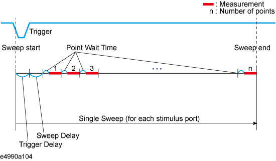
Time delay can be set for the period before sweep or actual measurement starts after the measurement signal is applied to the DUT. This function is useful, for example, when a certain period is required before the characteristics of the DUT become stable after the signal is applied, such as crystal resonators. Another application of this function is to observe changes in the impedance of the DUT in the time domain for a long span.
The time delay for each measurement points can be set by either or both of following two methods. The time delay is defined as follows. The sweep time in softkey is not the total sweep time.
Point Wait Time = Point Delay + (Sweep Time/Number of points)
Maximum point delay time is 30 seconds.
Total wait time for each point is maximum 67 seconds. If it is exceeded, an error occurs.
Waiting time is applied each time when iteration is caused due to impedance ranging or when using auto level control (ALC).
This function is useful to reduce the effect of stimulus condition changing when measuring the slow response devices. (It’s useful even in the measurement with span 0.)
Press Sweep Setup > Point Delay and input the desired time delay at a point.
Press Sweep Setup > Sweep Time and input the desired time.
When the trigger mode is set at "On Sweep"
When the trigger mode is set at "On Point".
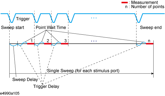
Time delay can be set at the point before sweep starts. This is useful when extra waiting time is required to control the effect to the DUTs when starting the new sweep. (It is common that the stimulus condition like frequency or OSC level changes lot when the instrument finishes the previous sweep and returns to the first point of sweep.)
Press Sweep Setup to display the Sweep Setup menu.
Press Sweep Delay and input the desired sweep time delay.
Maximum sweep delay time is 30 seconds.
Total wait time for each point is maximum 67 seconds. If it is exceeded, an error occurs.
Time delay can be set when the E4990A needs to change its internal circuit or reset null-loop. This is useful when extra waiting time is required to stabilize the measurement fluctuation due to DUT time constant characteristic.
Press System > Meas Setup > Band Delay.
Input the desired band change delay.
Press Avg to display the Averaging menu.
Press Meas Time and select the desired measurement speed time. The available options are 1|2|3|4|5 with 1 being the fastest time (maximized speed) and 5 being the most precise (accuracy maximized).
Setting a greater measurement time will improve measurement accuracy, but keep in mind that this requires a longer measurement time.
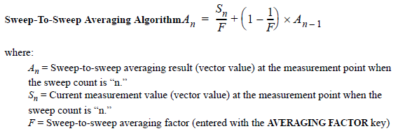
Sweep-to-sweep averaging computes each data point (vector value) based on an exponential average of consecutive sweeps weighted by a user-specified averaging factor. The sweep-to-sweep uses the algorithm shown below:
Perform the averaging factor setup as follows:
Press Avg to display the Averaging menu.
Press Avg Factor and input the desired averaging factor value.
The sweep-to-sweep averaging can be set to any natural number from 1 to 999. Setting the sweep-to-sweep averaging to 1 is equivalent to turning the averaging OFF (Averaging > OFF).
Press Averaging and toggle between the ON|OFF selection to turn ON/OFF the sweep-to-sweep averaging factor.
When the sweep-to-sweep averaging is turned ON, the value of sweep-to-sweep averaging that has been performed for the trace is shown on the instrument status bar. The sweep-to-sweep averaging starts once its turned ON (Averaging > ON) or after pressing the Averaging Restart key. When the averaging starts, “0” is displayed for the averaging count because the number of traces (sweep data) to be swept is always set to 0 at the initial state. Then the count increases by 1 as each sweeping ends. After the count reaches the number specified by the Avg Factor key, it stays constant while sweeping continues.
The averaging trigger function is used to execute the sweep the number of times specified by the averaging factor with a single trigger when the sweep averaging function is ON.
|
Averaging Trigger |
Function |
|
ON |
Performs the sweep the number of times specified by the averaging factor with a single trigger. |
|
OFF |
Performs the sweep once with a single trigger. |
The averaging factor is cleared before the start of measurement.
When the sweep averaging function is ON, follow these steps to set the averaging trigger function.
Press Avg to display the Averaging menu.
Press Avg Trigger and select ON to activate the averaging trigger.
Press Trigger.
Press Single. The averaging factor is cleared before the start of measurement, the sweep is executed the number of times specified by the averaging factor, and then the instrument waits for the next trigger.
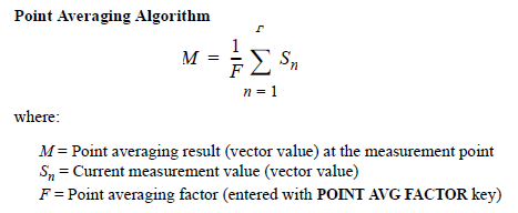
Point averaging averages each data point by a user-specified averaging factor. The Keysight E4990A repeatedly measures the same point until the averaging factor is reached. It then divides the vector summation of the measurement value by the averaging factor and starts measuring the next point. The sweep time increases in proportion to the averaging factor.
The algorithm used for point averaging is shown below:
Perform the averaging factor setup as follows:
Press Avg to display the Averaging menu.
Press Point Avg Factor and input the desired point averaging factor value.
Press Point Avg and toggle between the ON|OFF selection to turn ON/OFF the point averaging factor.