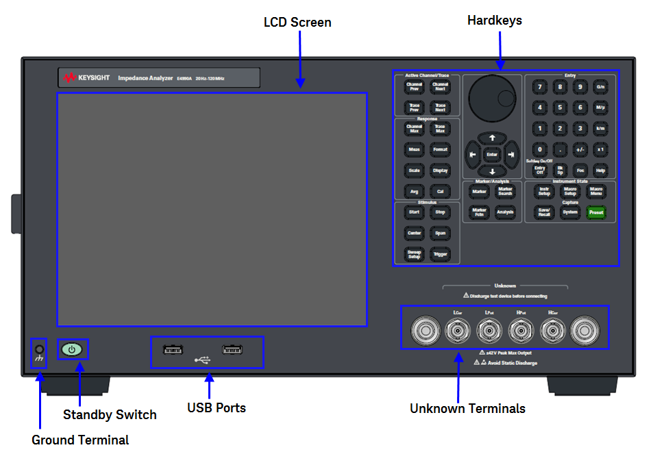
Ground terminal is provided with the E4990A and is connected to the chassis of the E4990A. You can connect a banana-type plug to this terminal for grounding.
A group of keys for selecting active channels and traces. For more on the concepts of channels and traces, see Setting Channels and Traces.
|
Hardkey Name |
Description |
|
Channel Next |
Selects the next channel as the active channel. (Each time the key is pressed, the active channel steps up from the current channel to the channel with one number larger than the current channel number). A channel must be active before you can define such parameters as the sweep range. To change the settings of a channel, use this key to first make the channel active. |
|
Channel Prev |
Selects the previous channel as the active channel. (Each time the key is pressed,the active channel steps down from the current channel to the channel with one number smaller than the current channel number). |
|
Trace Next |
Selects the next trace as the active trace. (Each time the key is pressed, the active trace steps up from the current trace to the trace with one number larger than the current trace number). A trace must be active before you can define measurement parameters and other settings. To change the settings of a trace, use this key to first make the trace active. |
|
Trace Prev |
Selects the previous trace as the active trace. (Each time the key is pressed, active trace steps down from the current trace to the trace with one number smaller than the current trace number). |
A group of keys used for entering numeric data is provided on the front panel of the E4990A.
|
Hardkey Name |
Description |
|
0, 1, 2, 3 , ...... , 9, ... Keys (numeric keys) |
Type numeric characters or a decimal point at the position of the cursor in the data entry area. |
|
+/- |
+/- alternately changes the sign (+, -) of a numeric value in the data entry area. |
|
G/n, M/u, k/m, x1
|
Adds a prefix to the numeric data typed by using the numeric key and +/- key. One of the two prefixes written on the surface of the key is automatically selected depending on the parameter to be entered. x1 is entered without a prefix. |
|
Softkey On/Off , Entry Off |
Turns off the data entry bar if it is displayed. If the dialog box is displayed, it cancels the entry and closes the dialog box. If the data entry bar and dialog box are not displayed, it turns the softkey menu display on/off. |
|
Bk Sp |
Backspace key. |
|
Foc |
Changes the selection (focus) among the objects to be manipulated by the NAVIGATION Block keys and ENTRY Block keys. The objects to be manipulated by the NAVIGATION Block keys and ENTRY Block keys include softkey menus, data entry areas, tables (e.g., segment tables, limit tables, and marker tables), and dialog boxes. When two or more of these objects are displayed on the screen and need selecting, use this key to change the selection (focus) among the objects to be manipulated. When a softkey menu is selected, the menu name area at the top of the menu is displayed in blue. When a data entry area is selected, the data entry bar is displayed in blue. When a table is selected, the frame of the table window is displayed in light gray. While a dialog box is displayed, the focus is fixed on the dialog box and cannot be changed. |
|
Help |
Displays help for E4990A. |
A group of keys related to the macro function, store and call function, control management function, and presetting of the E4990A (returning it to the preset state).
|
Hardkey Name |
Description |
|
Instr Setup |
Displays the short-cut keys to make quick setup. |
|
Macro Setup |
Displays the Macro Setup Menu in Softkey Menu Bar. |
|
Macro Menu |
Displays macro list to be executed which is registered in the macro setup. |
|
Save/Recall |
Displays the Save/Recall Menu in Softkey Menu Bar. Manipulating the Save/Recall Menu enables you to store the setup conditions to or read from the storage devices, calibration data, and trace data of the analyzer. |
|
Capture/System |
First, temporarily saves the data for the image displayed on the LCD screen the moment this key is pressed to the internal memory (clipboard). Immediately after that, displays the System Menu in Softkey Menu Bar. Manipulating the System Menu enables you to define the setup for the limit test and then execute it, or to define the setup for the control and management of the analyzer. Using the Dump Screen Image option enables you to store the image data in the clipboard to a file on the storage devices. Also, using the Print option in the System menu enables you to print the image data in the clipboard to a printer. |
|
Preset |
One message will prompt on the screen display and click OK in the message to return the analyzer to the initial setup state, called as factory state. |
A group of keys used for analyzing the measurement results by using the markers and etc.
|
Hardkey Name |
Description |
|
Marker |
Displays the Marker Menu in Softkey Menu Bar. Manipulating the Marker Menu enables you to turn the markers on/off and move them by entering stimulus values. You can place up to 10 markers on each trace. |
|
Marker Search |
Displays the Marker Search Menu in Softkey Menu Bar. Manipulating the Marker Search Menu enables you to move a marker to a specific point (maximum, minimum, peak, and a point with a target value) on a trace. You can also find the bandwidth parameters (up to six) and display them. |
|
Marker Fctn |
Displays the Marker Function Menu in Softkey Menu Bar. Manipulating the Marker Function Menu enables you to not only specify the marker sweep range and the coupling of markers on a channel but also to display statistics data on traces. |
|
Analysis |
Displays the Analysis Menu in Softkey Menu Bar. Manipulating the Analysis Menu enables you to use the analytical function of the Equivalent Circuit and each limit test. |
The following descriptions show how the NAVIGATION Block keys work both when the focus is on a softkey menu and when the focus is on the data entry area. For more on tables and dialog boxes manipulation, refer to the manipulation procedure for each of these functions.
When the focus is placed on a softkey menu (the menu title area in the uppermost part is displayed in blue), the NAVIGATION Block keys work as described below.
|
Hardkey Name |
Description |
|
|
Moves the softkey selection (highlighted display) up or down. |
|
|
Moves the softkey selection (highlighted display) up or down. |
|
|
Displays the softkey menu one layer above. |
|
|
Displays the softkey menu one layer below. |
|
Enter or |
Executes the function of the selected softkey. |
After pressing the data entry softkey, the focus automatically moves to the data entry area.
When the focus is placed on the data entry area (the data entry bar is displayed in blue), the NAVIGATION Block keys work as described below.
|
Hardkey Name |
Description |
|
|
Increases or decreases the numeric value in the data entry area in small steps. |
|
|
Increases or decreases the numeric value in the data entry area in large steps. |
|
|
Moves the cursor (|) in the data entry area laterally back and forth. Use it together with the ENTRY Block keys to change data one character at a time. |
|
Enter or |
Finishes the entry in the data entry area and moves the focus to the softkey menu. |
A group of keys used mainly for setting up response measurements on the E4990A.
|
Hardkey Name |
Description |
|
Channel Max |
Changes between normal and maximum display of the active channel window. In normal display, all of the defined channel windows (both active and non-active) are displayed in split views on the screen. In maximum display, only the active channel window is displayed over the entire area, with non-active windows not displayed. To maximize the active channel, double-click the channel window frame. Measurements are also carried out on the non-active channels that are not displayed. |
|
Trace Max |
Changes between normal and maximum display of the active trace window. In normal display, all of the defined trace windows (both active and non-active) are displayed in split views on the screen. In maximum display, only the active trace is displayed over the entire channel window, with non-active traces not displayed. To maximize the trace, double-click anywhere in the channel window. Measurements are also carried out on the non-active traces that are not displayed. |
|
Meas |
Displays the Measurement Menu in Softkey Menu Bar. Manipulating the Measurement Menu enables you to specify the measurement parameters (types of S-parameters) for each trace. |
|
Format |
Displays the Format Menu in Softkey Menu Bar. Manipulating the Format Menu enables you to specify the data format (data transformation and graph formats) for each trace. |
|
Scale |
Displays the Scale Menu in Softkey Menu Bar. Manipulating the Scale Menu enables you to specify the scale for displaying a trace (magnitude per division, value of the reference line, etc.) for each trace. You can also specify the electrical delay and phase offset for each trace. |
|
Display |
Displays the Display Menu in Softkey Menu Bar. Manipulating the Display Menu enables you to specify the number of channels and the channel window array, the number and arrangement of traces, the setup for data math, etc. |
|
Avg |
Displays the Average Menu in Softkey Menu Bar. Manipulating the Average Menu enables you to define the averaging, smoothing, and IF bandwidth. |
|
Cal |
Displays the Calibration Menu in Softkey Menu Bar. Manipulating the Calibration Menu enables you to turn the calibration and error correction on/off and change definitions for calibration kits. |
A group of keys for defining the stimulus values (signal sources and triggers).
|
Hardkey Name |
Description |
|
Start |
Displays the data entry bar for specifying the start value of the sweep range in the upper part of the screen. (It also displays the Stimulus Menu for specifying the sweep range in Softkey Menu Bar.) |
|
Stop |
Displays the data entry bar for specifying the stop value of the sweep range in the upper part of the screen. (It also displays the Stimulus Menu in the same way as Start.) |
|
Center |
Displays the data entry bar for specifying the center value of the sweep range in the upper part of the screen. (It also displays the Stimulus Menu in the same way as Start.) |
|
Span |
Displays the data entry bar for specifying the span value of the sweep range in the upper part of the screen. (It also displays the Stimulus Menu in the same way as Start.) |
|
Sweep Setup |
Displays the Sweep Setup Menu in Softkey Menu Bar. Manipulating the Sweep Setup Menu enables you to specify the signal source power level, sweep time, number of points, sweep type, etc. |
|
Trigger |
Displays the Trigger Menu in Softkey Menu Bar. Manipulating the Trigger Menu enables you to specify the trigger mode and trigger source. You can specify the trigger mode for each channel. |
The E4990A is equipped with a 10.4-inch TFT color, touch-sensitive LCD screen for displaying traces, scales, settings, softkeys and other measurement related information. The touch screen LCD allows you to manipulate softkeys by touching the LCD screen directly with a finger. For more on the LCD screen, see Screen Area: Names and Functions of Parts.
Do not press the surface of the LCD screen with a sharp object (e.g., nail, pen, or screwdriver). Pressing the surface with a sharp-pointed object will damage the LCD screen surface or cause the screen to fail.
Valid pixels are 99.998 % and more. Below 0.002% of fixed points of black, blue, green or red are not regarded as failure.
This switch can turn on/off the E4990A. The color on the button shows the status as shown below:
|
Indicator Color |
Description |
|
Green |
Normal power on status. |
|
Orange |
Standby status. |
|
Red |
Illegal power on status. |
To turn off the power of the E4990A, be sure to follow the steps described below:
First, press this standby switch or send a shutdown command from the external controller to activate the shutdown process (the processing of software and hardware necessary to turn off the power supply). This will put the E4990A into the standby state.
Next, if necessary, turn off power supply to the Power Cable Receptacle (to LINE) on the rear panel.
Under normal use, never directly interrupt the power supply to the power cable receptacle on the rear panel when the power supply is on. Always keep the Line Switch (Always ON) at (|). Never turn it off (O).
If you directly interrupt the power supply to the power cable receptacle when the power supply is on, or turn off the Line Switch (Always ON), the shutdown process will not work. This could damage the software and hardware of the E4990A and lead to device failure.
Turning on the power supply after a faulty shutdown may cause the system to start up in a condition called "safe mode." If this occurs, first shut down the system to set it to the standby state and then turn on the power supply again to start up the system in normal mode.
These connectors let you connect the instrument with a device under test (DUT) via test accessories (such as an adapter, test fixture, or cable). These accessories adopt a four-terminal pair design, thereby enabling more accurate and wider-range dynamic measurements. Each test connector has a pair of holes for securing the test accessory to the instrument.
The test ports comply with Installation Category I of IEC 61010-1.
To prevent failure, do not apply DC voltage or current to the UNKNOWN terminals. Special care must be taken with capacitors since they may be charged. Be sure to connect the DUT to the UNKNOWN terminal (or test fixture) only after discharging them sufficiently.
Two USB (Universal Serial Bus) Ports are provided that can be used for connecting to USB keyboard, USB mouse, USB memory or a printer. Connecting a compatible printer to this port enables screen information on the E4990A to be printed. See Using USB for more detail.