Other topics about Calibration
The E4991B has five calibration/compensation functions as shown below:
|
Calibration/compensation functions |
Execution Method |
Effect |
|
Calibration of open/short/load |
All calibration data are measured by connecting three standards (open, short, and load) one-by-one to the desired reference plane (connector). This reference plane is called the calibration reference plane. |
The error factors within the area from the instrument body to the calibration reference plane are removed. If calibration is performed for the connector of the DUT, it is not necessary to execute any further calibration/compensation. |
|
Calibration of low-loss capacitor |
The calibration data are measured by connecting the low-loss capacitor to the calibration reference plane after completing the open/short/load calibration. This can only be executed when the 7-mm connector is used as the calibration reference plane. |
This decreases high Q (low-loss coefficient) above the frequency band near 1 GHz, which is difficult to decrease by only using open/short/load calibration. |
|
Port extension compensation*1 |
When the port is extended from the calibration reference plane by a coaxial cable, enter the delay time (sec.) of the extension as a numerical value and regard the corresponding extended portion as a distributed parameter circuit without loss. |
This compensates additional error caused by phase shift in the area of the port extended by the coaxial cable. |
|
Fixture electrical length compensation |
Electrical length is entered as a numerical value. Since the electrical length of an exclusive-use test fixture is registered in the E4991B, the necessary electrical length can be set by simply selecting the model number of the test fixture used. |
This compensates additional errors caused by phase shift at the test fixture. |
|
Compensation of open/short |
All compensation data are measured after bringing the tested device’s connecting terminal to the open and/or short state. |
This removes any additional measurement error caused by residual impedance in the test fixture. |
*1. Port extension compensation is not available when a Keysight text fixture is selected to use.
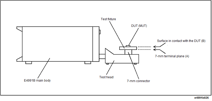
Before choosing which method of calibration and compensation to use, you must first decide where to set the calibration reference plane. The most common calibration reference plane is the 7-mm terminal plane in front of the test head. In this case, you may use open, short, load, and low-loss capacitor standards included in the calibration kit supplied with the E4991B. You may also use the terminal plane as a calibration reference plane for connecting the tested device. However, you need to use a calibration standard (working standard) that has a similar shape to the device under test.
|
Calibration Reference Plane |
Necessary Calibration/Compensation |
Place and Method of Execution |
|
7-mm terminal for test head*1 (A) |
1. Calibration for open/short/load |
Connect the coaxial terminal calibration kit to the coaxial terminal of the test head (calibration reference plane). |
|
2. Calibration of low-loss capacitor (This calibration is only used for such cases as high-Q measurement when high accuracy or consideration of low-loss factor is required at a frequency above approx. 1 GHz.) |
Connect the low-loss capacitor to the calibration reference plane.*2 |
|
|
3. Compensation for a fixture’s electrical length |
Enter this electrical length into the Keysight E4991B as data covering the area from the calibration reference plane to the tested device connecting plane.*3 |
|
|
4. Compensation of open/short |
Bring the tested device’s connecting terminal into the open and short states. |
|
|
Terminal for connecting to the DUT (B) |
Calibration of open/short/load |
Connect the working standard*4 to the tested device’s connecting terminal to make a calibration reference plane. |
*1. In extending the coaxial cable from the 7-mm terminal of test head to the test fixture, it is possible to compensate the port extension for the extended portion. For more on the port extension, see Port Extension Compensation.
*2. Since the low-loss capacitor is the 7-mm type, this calibration can only be executed when the calibration reference plane is a 7-mm terminal.
*3. When using an exclusive-use test fixture with a registered electrical length, you only need to select the model number of the fixture.
*4.This is a reference device that has a similar shape to the device under test.