Other topics about Temperature Characteristic test Kit (Option 007)
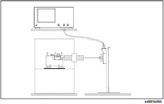
To measure temperature characteristics using the temperature characteristic test kit, connect the devices as shown in the below figure.
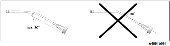
Use the heat-resistant measurement cable, keeping it straight where possible. If unavoidable, bent it gradually within 30° or less relative to the horizontal as shown in the left figure below.
Connect the extension cable after all the other settings are completed. After connected, the cable should be carefully handled. In particular, when you connect/disconnect the adapter and the N connector with the cable connected to the adapter or when you forcefully move the connected extension cable, the connector part is stressed and may be damaged.
Remove the test head from the E4991B.
First, remove the Type N connector connected to RF OUT. Then, turn both the Type N connectors connected to PORT1 and PORT2 at the same time to remove them.
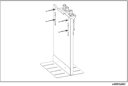
Secure the test head you removed to the test head holder.
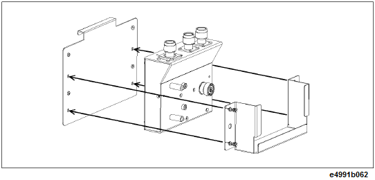
Mount the test head holder to the stand. At this time, do not secure it completely for later fine positioning.
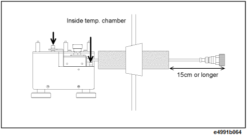
Insert the measurement cable into the hole in the temperature chamber so that the Type L, 7-mm connector side faces the inside of the temperature chamber. Attach heat insulating materials to the cable as necessary.
Adjust the position of the test fixture stand so that the length of the part of the measurement cable that is exposed to air outside the temperature chamber (refer to figure below) is 15 cm or longer, and install the measurement cable to the stand.
Adjust the position of the stand so that the 7-mm connector of the measurement cable and the 7-mm connector of the test head (DUT port) are located at the same height. In this step, fine adjust the position of the test head holder temporarily mounted and secure it tightly.
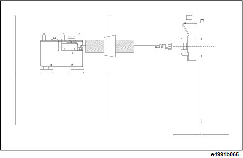
Connect the measurement cable and the test head.
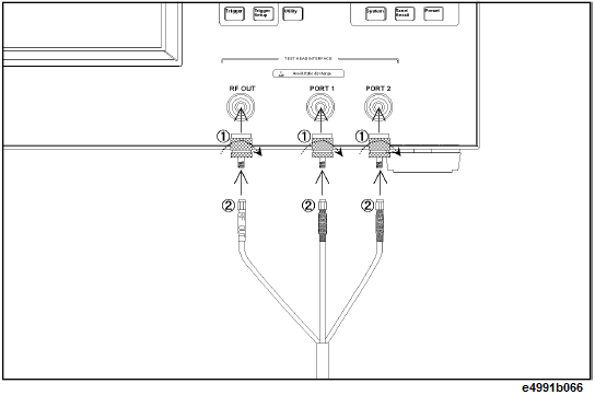
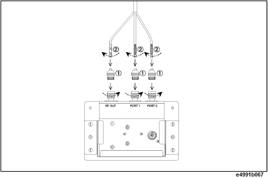
Connect the N (male) - 3.5 mm (female) adapters to RF Out, Port 1, and Port 2 on the E4991B and then connect the cables to the corresponding ports whose names are written on the extension cable.
To avoid damage to the connectors of the extension cable, be sure to connect the adapters to the E4991B first, and then connect the extension cable to the adapters.
Connect the N (female) - 3.5 mm (female) adapters to RF Out, Port 1, and Port 2 on the test head and then connect the cables to the corresponding ports whose names are written on the extension cable.
To avoid damage to the connectors of the extension cable, be sure to connect the adapters to the test head first, and then connect the extension cable to the adapters.
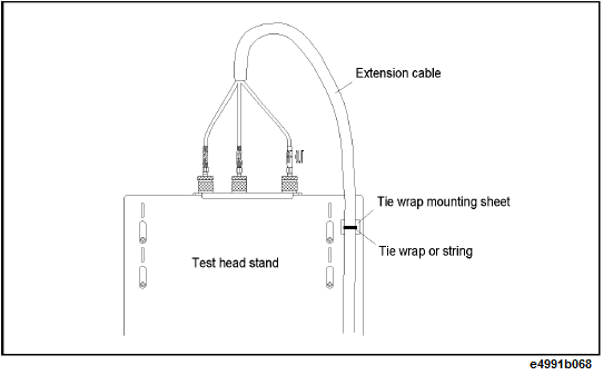
To decrease stress on the connector part due to the move of the extension cable, stick the attached mount cable tie (1400-0584) to an appropriate position, and use tie wraps or strings to tie the extension cable to the seat for securing.
When routing the extension cable downward, be sure to secure it at an upper part of the stand. When you need to route the extension cable downward (for example, when placing the E4991B by the test head stand), the weight of the cable itself may stress the connector part. To decrease this overload, secure the extension cable at an upper part of the stand as shown in figure below.