After turning the power ON, be sure to connect the 0 S (OPEN), 0 Ω (SHORT), 50 Ω (LOAD), and low-loss capacitor (optional) to the calibration reference plane and perform calibration. The calibration reference plane of the E4991B is usually the 7-mm terminal of the test head. This step is done to ensure that the calibration reference plane meets the specified measurement accuracy.
Calibration and fixture compensation data are measured at either fixed frequency points (initial setting) and user-defined points. See Selecting Calibration/Compensation Data Points. The fixed frequency point is used in this procedure.
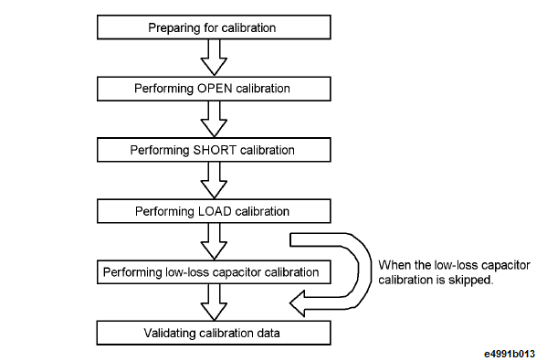
The basic procedure for the calibration is illustrated below:
Prepare for calibration by following these steps.
Press Cal > Cal Compen > Cal/Compen Point > Fixed freq.
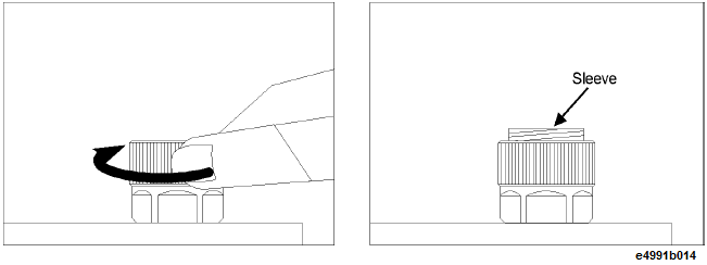
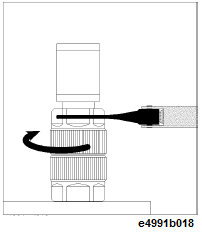
Turn the 7-mm connector nut of the test head clockwise until the connector sleeve is fully extended, as shown below.
Use the 0 S (OPEN) standard to perform OPEN calibration by following the procedure described below:
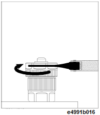
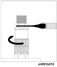
Turn the 0 S (OPEN) standard clockwise with the provided torque wrench to connect it securely to the 7-mm terminal, as shown below.
Press Cal > Calibration > Execute Cal > Open.
A check mark, √ appears on the left side of Open softkey upon completion of the OPEN calibration data measurement.
Turn the 0 S (OPEN) standard counterclockwise to remove it.

Use the 0 Ω (SHORT) standard to perform SHORT calibration by following these steps:
Turn the 0 Ω (SHORT) standard clockwise with the provided torque wrench to connect it securely to the 7-mm terminal, as shown below.
Press Cal > Calibration > Execute Cal > Short.
A check mark, √ appears on the left side of Short softkey upon completion of the SHORT calibration data measurement.
Turn the 0 Ω (SHORT) standard counterclockwise to remove it.
Use the 50 Ω (LOAD) standard to perform LOAD calibration by following these steps.
Turn the outside connector nut of the 50 Ω (LOAD) standard counterclockwise to fully retract the inside connector sleeve, as shown below.
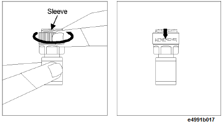
Turn the 50 Ω (LOAD) standard clockwise with the provided torque wrench to connect it securely to the 7-mm terminal, as shown below.
Press Cal > Calibration > Execute Cal > Load.
A check mark, √ appears on the left side of Load softkey upon completion of the LOAD calibration data measurement.
Turn the 50 Ω (LOAD) standard counterclockwise to remove it.
The LOW-LOSS CAPACITOR calibration should be performed for high Q (or low D: dissipation factor) measurements at high frequencies. The LOW-LOSS CAPACITOR calibration allows high accuracy for phase measurements. This calibration can be skipped if you do not need it for your purposes.
Turn the LOW-LOSS CAPACITOR clockwise with the provided torque wrench to connect it securely to the 7-mm terminal, as shown below.
Press Cal > Calibration > Execute Cal > Low Loss C (Optional).
A check mark, √ appears on the left side of Low Loss C (Optional) softkey upon completion of the LOW-LOSS CAPACITOR calibration data measurement.
Turn the LOW-LOSS CAPACITOR counterclockwise to remove it.
After completing all calibration data measurement, the calibration coefficients are calculated from the measured calibration data. The coefficients are automatically saved to the internal memory.
Confirm that all of the calibration data measurement is completed and then press Done.
If you want to abandon the measured calibration data, press Cal > Calibration > Execute Cal > Cancel before pressing Done. Turning the power OFF also resets the calibration data.
Verify that the display of the status bar on the bottom of the screen changes to COR.
When the measurement points for calibration/compensation are user-defined frequency points, Cor appears instead of want COR. If LOW-LOSS CAPACITOR calibration is performed, + is added like COR+.