Show 

Setting Video Trigger

You must set up the video trigger when you select either Wide Video, Narrow Video or Narrow2 Video for the trigger source. You do not have to set up the video trigger when you select other trigger sources.

The E5052B video trigger includes the following functions:

Follow the steps below to set up the video trigger for the transient measurement:

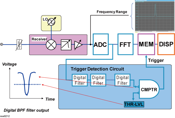
  1. The following figure is a simplified block diagram of the E5052B transient measurement mode as well as the frequency boundary trigger (Video trigger) detection circuit.


    The RF signal comes out of the receiver section, which is downconverted to an IF signal, and goes into the ADC. The digitized incoming data with available sampling rate of the ADC, with a maximum rate of 125 MSa/s. The data is fed into the FFT section to obtain frequency data and then recorded in the internal memory. The data is recorded continuously similar to an endless tape recorder if there is no trigger signal present.

    The digitized data is also fed into the trigger detection circuit. The circuit consists of several stages of digital filter and a digital comparator. The digitized voltage data coming out of the trigger detection circuit is compared to the threshold level for triggering. In the frequency boundary out mode, the output signal of the digital filter stage is shown in the figure above. When the frequency goes out of the frequency boundary, the voltage of the digitized data drops accordingly.

  2. The method of data processing for obtaining measurement values of frequency transient and judging the condition of video trigger is different due to different data processing time. Data processing of measurement values is done after measurement is completed, while video trigger requires real-time processing during measurement. Therefore, the following things happen.

      • The instrument is not triggered even though the conditions seem to be satisfied.

      • The instrument is triggered even though the conditions seem not to be satisfied.

In this case, change the power level of video trigger and frequency bandwidth to adjust the sensitivity of trigger. In addition, if the instrument is triggered even though the condition is not satisfied, improve the time resolution. This enables to see the frequency change that had not been seen before and to investigate the cause.

  1. The trigger standby band is determined based on a specified trigger frequency. Setting of a center frequency of the trigger standby band has limitation and therefore, the trigger frequency is not necessarily the same as the center frequency of the standby band. In this case, the standby band whose center frequency is closest to the specified trigger frequency is selected.

    This standby band consists of two bands based on its center frequency: low frequency side and high frequency side. When the video mode is positive, the instrument is triggered when an input signal comes in the low frequency side and then high frequency side. When the video mode is negative, the instrument is triggered when an input signal comes in the high frequency band and then low frequency band. Adjustment is made at the timing of post processing so that the point when an input signal cuts across the trigger frequency becomes the zero point of the time-axis.

      •  Wide-Narrow mode:

        • Frequency range of narrow is 25.6 MHz

        • Time spans of wide and narrow are the same

        • Advanced Mode for narrow is OFF

      • Narrow-Narrow mode:

        • The frequency range and time span for both channels are the same.

        • Advanced Mode for narrow is OFF

Setting for Wide Band

  1. Press Setup > Video Trigger > Wide Video Mode > OUT | IN | Positive | Negative

Mode

Description

IN

The instrument is triggered when the input signal comes in the trigger standby band.  

Adjustment is made so that the first measurement point when a signal comes in the standby band becomes the zero point of the time-axis.

When the video trigger is selected in this mode, two dotted lines indicating the upper and lower limits of the standby band are displayed on the graph of the frequency measurement.

OUT

The instrument is triggered when the input signal is outside the trigger standby band.

Adjustment is made so that the first measurement point when a signal goes outside the band becomes the zero point of the time-axis.

When the video trigger is selected in this mode, two dotted lines indicating the upper and lower limits of the standby band are displayed on the graph of the frequency measurement.

POSitive

The instrument is triggered when an input signal cuts across the trigger standby frequency from the lower frequency side to the higher frequency side.

Adjustment is made so that the point when an input signal cuts across the standby frequency becomes the zero point of the time-axis.

When the video trigger is selected in this mode, three dotted lines indicating the standby frequency, the upper limit and lower limit of the standby band are displayed on the graph of the frequency measurement.       

NEGative

The instrument is triggered when an input signal cuts across the trigger standby frequency from the higher frequency side to the lower frequency side.

Adjustment is made so that the point when an input signal cuts across the standby frequency becomes the zero point of the time-axis.

When the video trigger is selected in this mode, three dotted lines indicating the standby frequency, the upper limit and lower limit of the standby band are displayed on the graph of the frequency measurement.

  1. Press Setup > Video Trigger > Wide Freq.

  2. Enter the center frequency of the video trigger in the data entry field that appears in the upper part of the screen.
     

    Trigger Mode

    Description

    IN/OUT

    The center frequency of the trigger standby band.

    The value that can be set is a discrete value and the setting step is decided by the width of the trigger detection frequency.

    POSitive / NEGative

    The trigger standby frequency.

    Any frequency within the measurement range can be set.

  3. Press Setup > Video Trigger > Wide Width

Assuming that max_width = fspan (span of the frequency range) × 1.1, choices of width for each range are as follows:
 

Trigger Mode

Frequency Range Span

IN/OUT

max_width, max_width/2, max_width/4, max_width/8, max_width/16, max_width/32, max_width/64

POSitive / NEGative

max_width/8, max_width/16, max_width/32

  1. For example: When the range is 400 M - 1.2 GHz, fspan = 1.2 G - 400 M =800 MHz, max_width = 800M × 1.1 = 880 MHz,choices of width are 880 MHz, 440 MHz, 220 MHz, 110 MHz, 55 MHz, 27.5 MHz, and 13.8 MHz.

  1. This setting is restricted by the settings of frequency band or maximum fre-quency of the input signal.

    The setting is enabled when you select Wide Video from the trigger source options.

Setting for Narrow Band

  1. Press Setup > Video Trigger > Narrow Video Mode ( or Narrow2 Video Mode) > OUT | IN | Positive | Negative

Mode

Description

IN

The instrument is triggered when the input signal comes in the trigger standby band.  

Adjustment is made so that the first measurement point when a signal comes in the standby band becomes the zero point of the time-axis.

When the video trigger is selected in this mode, two dotted lines indicating the upper and lower limits of the standby band are displayed on the graph of the frequency measurement.

OUT

The instrument is triggered when the input signal is outside the trigger standby band.

Adjustment is made so that the first measurement point when a signal goes outside the band becomes the zero point of the time-axis.

When the video trigger is selected in this mode, two dotted lines indicating the upper and lower limits of the standby band are displayed on the graph of the frequency measurement.

POSitive

The instrument is triggered when an input signal cuts across the trigger standby frequency from the lower frequency side to the higher frequency side.

Adjustment is made so that the point when an input signal cuts across the standby frequency becomes the zero point of the time-axis.

When the video trigger is selected in this mode, three dotted lines indicating the standby frequency, the upper limit and lower limit of the standby band are displayed on the graph of the frequency measurement.       

NEGative

The instrument is triggered when an input signal cuts across the trigger standby frequency from the higher frequency side to the lower frequency side.

Adjustment is made so that the point when an input signal cuts across the standby frequency becomes the zero point of the time-axis.

When the video trigger is selected in this mode, three dotted lines indicating the standby frequency, the upper limit and lower limit of the standby band are displayed on the graph of the frequency measurement.

  1. Press Setup > Video Trigger > Narrow Freq (or Narrow2 Freq).

  2. Enter the center frequency of the video trigger in the data entry field that appears in the upper part of the screen.

Trigger Mode

Description

IN/OUT


The center frequency of the trigger standby band.

The value that can be set is a discrete value and the setting step is decided by the width of the trigger detection frequency.

POSitive / NEGative

The trigger standby frequency.

Any frequency within the measurement range can be set.


  1. Press Setup > Video Trigger > Narrow Width ( or Narrow2 Width).

Trigger Mode

Frequency Range

Width

IN/OUT

80MHz

85MHz, 55MHz, 27.5MHz, 13.8MHz, 6.88MHz, 3.44MHz, 1.72MHz, 859kHz, 430kHz, 215kHz

25.6MHz

27.5MHz, 13.8MHz, 6.88MHz, 3.44MHz, 1.72MHz, 859kHz, 430kHz, 215kHz, 107kHz, 53.7kHz

1.6MHz

1.72MHz, 859kHz, 430kHz, 215kHz, 107kHz,  53.7kHz, 26.9kHz, 13.4kHz, 6.71kHz, 3.36kHz

200kHz

215kHz, 107kHz,  53.7kHz, 26.9kHz, 13.4kHz, 6.71kHz, 3.36kHz, 1.68kHz, 839Hz, 420Hz  

25kHz

26.9kHz, 13.4kHz, 6.71kHz, 3.36kHz, 1.68kHz, 839Hz, 420Hz, 210Hz, 105Hz, 52.5Hz

3.125kHz

3.36kHz, 1.68kHz, 839Hz, 420Hz, 210Hz, 105Hz, 52.5Hz, 26.2Hz,  13.1Hz,  6.56Hz

POSitive / NEGative

80MHz

13.8MHz, 6.88MHz, 3.44MHz  

25.6MHz

3.44MHz, 1.72MHz, 859kHz

1.6MHz

215kHz,  107kHz,  53.7kHz

200kHz

26.9kHz, 13.4kHz, 6.71kHz

25kHz

3.36kHz, 1.68kHz, 839Hz

3.125kHz

420Hz, 210Hz, 105Hz

  1. When the width is set to the whole measurement frequency range (the maximum one for each range), the setting value of the VIDeo:THReshold command indicates the threshold of the input signal power (Power trigger).

    In the POSitive/NEGative mode, the setting value of the FREQuency:CENTer command doesn't necessarily mean the center of the band range. In this case, the value nearest to the setting value of the FREQuency:CENTer that can be set is selected as the center frequency of the band.

    IN/OUT width updated in firmware A.03.10.

  1. Press Setup > Video Trigger > Minimum Power Level.

  2. Enter the minimum power level of the video trigger in the data entry field that appears in the upper part of the screen.

  3. This setting is restricted to the range of Narrow Band measurement that is determined by the target frequency and frequency range.

    The setting is enabled when you select Narrow Video (or Narrow2 Video) from the trigger source options.