Other topics about Communication with External Devices
This section shows the typical timing chart of I/O port Signal.
When the formatted data calculation is completed during the sweep, a negative pulse is provided. The pulse width of the sweep completion signal is shown in the figure below:

|
|
Typical value |
|
|
T1 |
Pulse width of /SWEEP END |
12 µs |
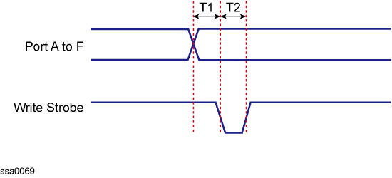
The figure below shows the timing chart for data output and write strobe signal output to ports A through F.

|
T1 |
Response time of write strobe signal |
1 µs |
|
T2 |
Pulse width of write strobe signal |
1 µs |

|
|
Minimum value |
|
|
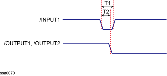
T1 |
Pulse width of /INPUT1 |
1 µs |
|
T2 |
Response time of /OUTPUT1, /OUTPUT2 |
0.5 µs |

|
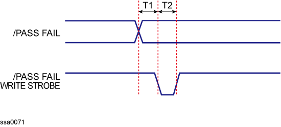
T1 |
Response time of /PASS FAIL write strobe signal |
1 µs |
|
T2 |
Pulse width of /PASS FAIL write strobe signal |
1 µs |