Other topics about Making Measurement
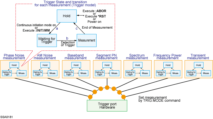
The trigger system is responsible for tasks such as detecting the start of a measurement cycle (triggering) and enabling/disabling measurement for each measurement. As shown in the following figure, the trigger system has three states for each measurement: “Hold,” “Waiting for Trigger ,” and “Measurement”. If any one of the measurements holds hardware and trigger port, other measurement will keep one of the states.
The E5052B has a trigger model for each measurement (see below); however, only one triggered measurement can take place at a time. This is because the hardware and the trigger port are shared by seven measurement interfaces. For example, even if the continuous initiation mode is enabled for all measurements and the trigger source is set to Internal, only one triggered measurement takes place.

When the windows couple is turned on, you cannot use TRIG:MODE.
The following subsections describe the states for each measurement and how the trigger system switches among the states.
When one of the following commands has been executed, the trigger system switches to “Hold” state, interrupting the measurement which is underway (arrow “e” in “d” in the Trigger System). When the power is turned on, the phase noise measurement is triggered, while the continuous initiation mode is set to ‘ON’ for the phase noise measurement and the trigger source is set to “Internal”.
• :ABORt
• *RST
During the “Hold” state, if either one of the following commands is executed or the measurement switches to the “Initiate” state by the front panel control, then the trigger system switches to the “Waiting for Trigger” state (arrow “f” in “a” in the Trigger System). “xx” specifies the measurements (PN, AM, BB, PS, SP, FP or TR) that are now waiting for trigger.
• :INITiate:xx:IMMediate
• :INITiate:xx:CONTinuous ON
The instrument is triggered (i.e., a trigger is detected) during the “Waiting for Trigger” state, and then the trigger system switches to the “Measurement” state (arrow “B” in “b” in the Trigger System).
As shown in the table below, how the instrument is triggered differs depending on which trigger source is specified.
|
Trigger Source |
How instrument is triggered |
|
Internal trigger |
The instrument is automatically triggered itself. |
|
External trigger |
The instrument is triggered when a trigger signal is fed through the Ext Trig terminal. |
|
Bus trigger |
The instrument is triggered when the *TRG command is issued. |
|
Manual trigger |
The instrument is triggered when you press [Trigger] - Trigger on the front panel. |
|
In using the wideband mode for the transient measurement, the instrument is triggered when the frequency of the measuring signal crosses the frequency value of the wideband trigger setting. |
|
|
In using the narrowband mode for the transient measurement, the instrument is triggered when the frequency of the measuring signal crosses the frequency value of the narrowband trigger setting. |
To set the trigger source, use the following command (“xx” specifies the measurements (PN,AM,BB,PS,SP,FP,TR) that are now waiting for trigger):
• :TRIGger:xx:SOURce
In the “Measurement” state, the instrument starts the measurement that was in the “Initiate” state immediately before the transition to this state.
If the delay time of DC control voltage and DC power voltage are set (by :SOURce:VOLTage:CONTrol:DELay, :SOURce:VOLTage:POWer:DELay), the instrument waits for the elapse of the sweep delay time before starting a measurement.
When the instrument has finished measuring, the trigger system behaves in one of the following ways depending on the setting of the continuous initiation mode.
|
Continuous Initiation Mode |
Trigger System Behavior |
|
OFF |
The trigger system switches to the “Hold” state; “c” in the Trigger System |
|
ON |
The trigger system switches to the “Hold” state and then to the “Waiting for Trigger” state; “c” and “a” in the Trigger System |