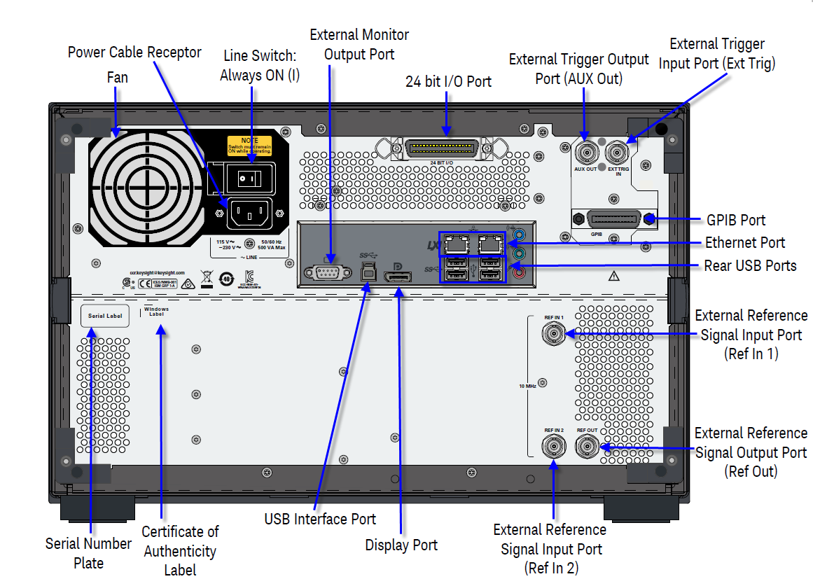
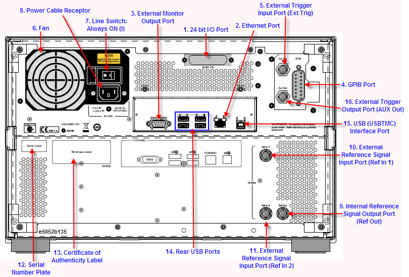
The terminal to which an automatic machine (handler) used on a production line is connected. See 24 bit I/O Port.
|
Specification |
Value |
|
Connector type |
36-pin D-Sub connector, Female |
|
Input Signal Level |
TTL level, (0 V to +5 V), Threshold Low: 0.5 V, High: 2.1V |
|
Trigger Pulse Width |
> 2 μs |
|
Trigger Polarity |
Positive/negative edge selectable |
A terminal for connecting the E5052B to a LAN (Local Area Network). Connecting this instrument to a LAN enables you to access the hard disk drive of this instrument from an external PC or to control this instrument by using SICL-LAN or telnet.
|
Specification |
Value |
|
Connector type |
8-pin RJ-45 connector |
|
Base standard |
10Base-T/100Base-T Ethernet (automatic data rate selection) |
A terminal to which an external color monitor (display device) can be connected.
[S/N prefix MY477/SG477 or above]
Connector type: Display Port and 15-pin VGA connector female.
By connecting a color monitor to this terminal, Keysight Technologies logo is shown on an external color monitor as the extended desktop.
When the same information shown on the LCD screen of the main body, Go to Windows -> Control Panel -> Appearance and Personalization -> Connect to an external display. Select “Duplicate these displays” at Multiple displays and then click Apply and OK.
[S/N prefix MY476/SG476 or below]
Connector type: 15-pin mini-D sub connector, Female.
By connecting a color monitor to this terminal, the same information shown on an external color monitor as the clone displays.
The connection of an external controller through General Purpose Interface Bus (GPIB) connector allows you to configure an automatic measurement system.
This GPIB connector is used only for controlling the E5052B from an external controller. Use USB/GPIB interface to control other devices from the E5052B. You cannot control other devices from the E5052B through this GPIB connector.
A connector to which external trigger signals are input. This connector detects the downward transition from the HIGH state in TTL signals as the trigger signal. To use this connector to generate a trigger, you must set the trigger source to the "external" side (key operation: Trigger > Source > External).
Connector type: BNC connector, female
The cooling fan for controlling the temperature inside the E5052B. This fan exhausts heated air from inside the analyzer to the outside.
Always keep this switch on (|).
Do not use this switch to turn off (O) the mains. Doing so may cause the analyzer to fail. For more information, see the description of the Standby Switch.
The receptacle (outlet) to which the power cable is connected.
To connect the device to a power source (outlet), use the supplied three-prong power cable with a ground conductor. The plug attached to the power cable (on the power outlet side or device side of the cable) serves as the disconnecting device (device that cuts off power supply) of the E5052B. When the power supply must be cut off to avoid such danger as electric shock, pull out the power cable plug (on the power outlet side or device side of the cable). For the procedure for turning off the mains in normal use, see the description in Standby Switch.
For more on the power supply, see the Installation Guide.
A connector for outputting the internal frequency reference signal from the E5052B. By connecting this output connector to the external reference signal input connector of another device, the device can be phase-locked to the internal reference signal of the E5052B and used under this condition.
|
Specification |
Value |
|
Connector type |
BNC connector, female |
|
Output signal (Typical) |
10 MHz ± 5Hz, +2.5 dbm ± 2.5 dBm |
|
Output impedance (Typical) |
50 ohm |
When a reference signal is inputted to "Ref In2" and Ch2 is locked with this signal, the "Ref Out" outputs the same signal.
The reference signal input connector is used for phase-locking the measurement signal from the E5052B to the external frequency reference signal. Inputting the reference signal to this connector improves the accuracy and frequency stability of the measurement signal from the E5052B. This port is available in the phase noise measurement, segment phase noise measurement and transient measurement (narrow-narrow mode).
|
Specification |
Value |
|
Connector type |
BNC connector, female |
|
Input signal (Typical) |
10 MHz ± 10 Hz, 0 dBm to +10 dBm |
In the phase noise measurement and segment phase noise measurement, the external reference signal can be used, when the "Ref. Osc.1 Source" function is set to "External". When the frequency reference signal is input to this connector, the measurement signal from the E5052B is automatically phase-locked to the reference signal. When an input signal is not present, the frequency reference signal inside the E5052B is automatically used. The ExtRef1 on the instrument status bar is displayed in blue when the system is phase-locked to the external reference signal and in gray when not phase-locked.
When Narrow-Narrow mode in the transient measurement is selected, this connector should be connected with the Ref Out connector. The error message of "291 Ref In 1 input not detected" is displayed when the clock signal is not input into this connector.
The reference signal input connector is used for phase-locking the measurement signal from the E5052B to the external frequency reference signal. Inputting the reference signal to this connector improves the accuracy and frequency stability of the measurement signal from the E5052B. This port is available in all measurement functions of E5052B.
|
Specification |
Value |
|
Connector type |
BNC connector, female |
|
Input signal (Typical) |
10 MHz ± 10 Hz, 0 dBm to +10 dBm |
In the phase noise measurement and segment phase noise measurement, the external reference signal can be used when the "Ref. Osc.2 Source" function is set to "External". In other measurement functions, the external reference signal can be used without any setting. When the frequency reference signal is input to this connector, the measurement signal from the E5052B is automatically phase-locked to the reference signal. When an input signal is not present, the frequency reference signal inside the E5052B is automatically used. The ExtRef2 on the instrument status bar is displayed in blue when the system is phase-locked to the external reference signal and in gray when not phase-locked.
The seal showing the serial number of the product.
The label showing the information of the "Certificate of Authenticity."
Two USB (Universal Serial Bus) ports are provided specifically for USB/GPIB interface or a printer.
The specifications of this port are identical to the Front USB Port.
Through this port, you can control the E5052B from external controllers. For more information on the measurement system using the USB port, see the USB Remote Control System.
|
Specification |
Value |
|
Connector type |
Universal serial bus (USB) jack, type B (4 contact positions), Female |
|
Compliance Standards |
USBTMC-USB488 and USB2.0 |
External Trigger Output port outputs the pulse of a specified polarity at the end of measurement (EOM).
This port can handle maximum output current of 50mA.The port outputs to the connector through 24 Ohm resistance and 10k ohm pull-up resistance in series with the output of 74ACT14.
|
Symbol |
Parameter |
Typical |
Condition |
|
|
|
Pulse Width |
1 |
uSec |
|
|
VOH |
HIGH Level Output Voltage |
5 |
Volt |
Iout=-50uA |
|
VOL |
LOW Level Output Voltage |
0 |
Volt |
Iout=50uA |