Used for choosing between power-on ( | ) and standby (O) state of E5052B.
To turn off the power for the E5052B, be sure to follow the steps described below:
First, press this standby switch or send a shutdown command from the external controller to activate the shutdown process (the processing of software and hardware necessary to turn off the power supply). This will put the E5052B into the standby state.
Next, if necessary, turn off power supply to the Power Cable Receptacle (to LINE) on the rear panel.
Under normal use, never directly interrupt the power supply to the power cable receptacle on the rear panel when the power supply is on. Always keep the Line Switch (Always ON) at (|). Never turn it off (O).
If you directly interrupt the power supply to the power cable receptacle when the power supply is on, or turn off the Line Switch (Always ON), the shutdown process will not work. This could damage the software and hardware of the E5052B and lead to device failure.
Turning on the power supply after a faulty shutdown may cause the system to start up in a condition called "safe mode." If this occurs, first shut down the system to put it into the standby state and then turn on the power supply again to start up the system in normal mode.
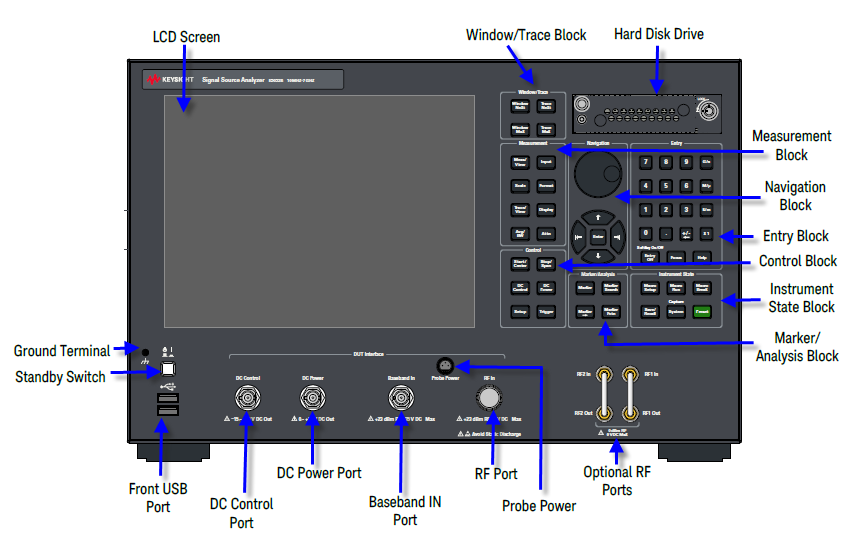
The E5052B is equipped with a 10.4-inch TFT color, touch-sensitive LCD screen for displaying traces, scales, settings, softkeys and other measurement related information. The touch screen LCD allows you to manipulate softkeys by touching the LCD screen directly with a finger. For more on the LCD screen, see Screen Area: Names and Functions of Parts.
Do not press the surface of the LCD screen with a sharp object (e.g., a nail, pen, or screwdriver). Pressing the surface with a sharp-pointed object will damage the LCD screen surface or cause the screen to fail.
Occasionally, a few pixels may appear on the screen as a fixed point of blue, green or red. Please note that this is not a failure and does not affect the performance of your product.
A group of keys for selecting active measurement windows and traces. For more on the concepts of measurement windows and traces, see Setting Trace layout.
|
Key Name |
Description |
|
Window Next Key |
Pressing this key causes the active measurement window to switch over to the next higher window number of seven measurement windows. It is possible to define sweep range and other parameters of an active measurement window. To change the settings of a window, use this key to first activate the window. |
|
Window Max Key |
Switches over between normal and maximum display of the active measurement window. In normal display, all seven measurement windows (both active and non-active) are displayed in split views on the screen. In maximum display, only the active measurement window is displayed over the entire area, without showing non-active measurement windows. You can also switch over between the normal and maximum windows by double-clicking the measurement window frame. Measurements are also carried out on the non-active measurement windows that are not displayed. |
|
Trace Next Key |
Selects the next trace as the active trace. (Each time the key is pressed causes the active trace to step up from the trace with the currently designated number to one with a higher number.) An active trace is one for which the measurement parameters are defined. To change the settings for a trace, use this key to first make the trace active. |
|
Trace Max |
Switches over between normal and maximum display of the active trace within the measurement window. In normal display, all traces are displayed in split views on the measurement window. For the maximum display, only the active trace is maximized, while non-active traces are not displayed. To maximize the active trace, you can also double-click the area inside the measurement window (excluding the frame). Measurements are also carried out on the non-active traces that are not displayed. |
A group of keys used mainly for setting up measurements on the E5052B.
|
Key Name |
Description |
|
Meas/View Key |
Displays the Measurement View Menu in the right part of the screen. Manipulating in the Measurement View Menu enables you to select any active measurement window. Active measurement windows are also selectable in maximum display. In this case, the measurement window in maximum display will switch over to the one you have selected. |
|
Input Key
|
Displays the Input Menu in the right part of the screen. Manipulating the Input Menu enables you to select any port for the measurement signal input. |
|
Scale Key |
Displays the Scale Menu in the right part of the screen. Manipulating the Scale Menu enables you to specify the scale for displaying a trace (magnitude per division, value of the reference line, etc.) for each trace. |
|
Format Key |
Displays the Format Menu on the right side of the screen. Manipulating the Format Menu enables you to specify the data format (data transformation and graph formats) for each trace. |
|
Trace/View Key |
Displays the Trace View Menu in the right part of the screen. Manipulating the Trace View Menu enables you to specify the data smoothing, data saving on memory, title of trace, the setup for data math, etc. for each trace. |
|
Display Key |
Displays the Display Menu on the right side of the screen. Manipulating the Display Menu enables you to specify the marker information, measurement condition, update, the title label, etc. |
|
Avg/BW Key |
Displays the Average Menu in the right part of the screen. Manipulating the Average Menu enables you to specify enabling/disabling and number of times for averaging, etc. For spectrum measurements only, you can specify the bandwidth of resolution. |
|
Attn Key |
Displays the Attenuator Menu in the right part of the screen. Manipulating the Attenuator Menu enables you to change the setting of the input signal attenuator |
A group of keys for defining the values of DC output port, sweep and trigger settings.
|
Key Name |
Description |
|
Start/Center Key |
Displays the data input bar in the upper part of the screen by which you can specify the start value of the sweep range for the active measurement trace or the time offset value for the transient measurement. It also displays the menu in the right part of the screen that allows you to specify the sweep range. You can use the following menus:
|
|
Stop/Span Key |
Displays the data input bar in the upper part of the screen by which you can specify the stop value of the sweep range for the active measurement trace or the span value for the transient measurement. Also displays the menu in the right part of the screen that allows you to specify the sweep range. You can use the following menus:
In these menus, the titles are different from those at the start, but the function of the softkey is the same. |
|
DC Control Key |
Displays the DC Control Voltage Menu by which you can specify the values of control voltage output for the DC CONTROL port. |
|
DC Power Key |
Displays the DC Power Voltage Menu by which you can specify the values of power voltage output for the DC power port. |
|
Setup Key |
Displays the Setup Menu on the right side of the screen. Manipulating the Setup Menu enables you to specify the frequency range, IF gain, input level etc required for individual measurements. |
|
Trigger Key |
Displays the Trigger Menu on the right side of the screen. Manipulating the Trigger Menu enables you to specify the trigger mode and trigger source. You can specify the trigger mode for each measurement window. |
The E5052B comes with a removable hard disk drive. For removal procedure, see Removing/Mounting Removable Hard Disk.
The keys and knob in the NAVIGATION Block are used to navigate between softkey menus or selected (highlighted) areas in a dialog box and to change a numeric value in the data entry area by stepping up or down. When selecting one of two or more objects (softkey menus, data entry areas, etc.) to manipulate with the NAVIGATION Block keys displayed on the screen, first press the Focus key in the ENTRY Block to select the object to be manipulated (placing focus on the object) and then manipulate the NAVIGATION Block keys (knob) to move among selected (highlighted) objects or change numeric values.
The following descriptions show how the NAVIGATION Block keys work both when the focus is on a softkey menu and when the focus is on the data entry area. For more on manipulating tables and dialog boxes, refer to the manipulation procedure for each of these functions.
When the focus is placed on a softkey menu (the menu title area in the uppermost part is displayed in blue), the NAVIGATION Block keys work as described below.
|
Key Name |
Description |
|
|
Moves the softkey selection (highlighted display) up or down. |
|
|
Moves the softkey selection (highlighted display) up or down. |
|
|
Displays the softkey menu one layer above. |
|
|
Displays the softkey menu one layer below. |
|
|
Executes the function of the selected softkey. |
After pressing the data entry softkey, the focus automatically moves to the data entry area.
When the focus is placed on the data entry area (the data entry bar is displayed in blue), the NAVIGATION Block keys work as described below.
|
Key Name |
Description |
|
|
Increases or decreases the numeric value in the data entry area in small steps. |
|
|
Increases or decreases the numeric value in the data entry area in large steps. |
|
|
Moves the cursor (|) in the data entry area laterally back and forth. Use it together with the ENTRY Block keys to change data one character at a time. |
|
|
Finishes the entry in the data entry area and moves the focus to the softkey menu. |
A group of keys used for entering numeric data is provided on the front panel of the E5052B.
|
Key Name |
Description |
|
0, 1, 2, 3 ..... 9 , . |
Type numeric characters or a decimal point at the position of the cursor in the data entry area. |
|
+/- & |
+/- alternately changes the sign (+, - ) of a numeric value in the data entry area.
|
|
G/n, M/u, k/m, x1 |
Adds a prefix to the numeric data typed by using the numeric key and +/- key and then enters that data. One of the two prefixes written on the surface of the key is automatically selected depending on the parameter to be entered. x1 is entered without a prefix. |
|
Softkey On/Off , Entry Off Key |
Turns off the data entry bar if it is displayed. If the dialog box is displayed, cancels the entry and closes the dialog box. If the data entry bar and dialog box are not displayed, turns the softkey menu display on/off. |
|
Help Key |
Displays SSA help for E5052B. |
|
Focus Key |
Changes the selection (focus) among the objects to be manipulated by the NAVIGATION Block keys and ENTRY Block keys. The objects to be manipulated by the NAVIGATION Block keys and ENTRY Block keys include softkey menus, data entry areas, dialog boxes, VBA editor, other Window applications and Help window (if they are running). When two or more of these are displayed on the screen and need selecting, use this key to change the selection (focus) among the objects to be manipulated. When a softkey menu is selected, the menu name area at the top of the menu is displayed in blue. When a data entry area is selected, the data entry bar is displayed in blue. When a table is selected, the frame of the table window is displayed in light gray. While a dialog box is displayed, the focus is fixed on the dialog box and cannot be changed. |
A group of keys related to the macro function, store and call function, control/management function, and the presetting of the E5052B (returning it to the preset state).
|
Key Name |
Description |
|
Macro Setup Key |
Displays the Macro Setup Menu on the right side of the screen. Manipulating the Macro Setup Menu enables you to start up the VBA editor or to create, call, or store a VBA project. |
|
Macro Run Key |
Executes a VBA procedure called "main" that has a VBA module named Module1. |
|
Macro Break Key |
Stops the VBA procedure being executed. |
|
Save/Recall Key |
Displays the Save/Recall Menu on the right side of the screen. Manipulating the Save/Recall Menu enables you to store the setup conditions to or read from the storage devices, calibration data, and trace data of the analyzer. |
|
Capture/System Key |
First, temporarily saves the data for the image displayed on the LCD screen the moment this key is pressed to the internal memory (clipboard). Immediately after that, displays the System Menu on the right side of the screen. Manipulating the System Menu enables you to define the setup for the limit test and then execute it or to define the setup for the control and management of the analyzer. Using the Dump Screen Image option enables you to store the image data in the clipboard to a file on the storage devices. Also, using the Print option in the System menu enables you to print the image data in the clipboard to a printer. |
|
Preset Key |
Displays the Preset Menu on the right side of the screen. Clicking Factory in the Preset Menu enables you to return the analyzer to the initial setup state, called the preset setup. |
A group of keys used for analyzing the measurement results by using the markers, fixture simulator, etc. For more on the functions of the keys in the MKR/ANALYSIS Block, see Overview of Functions.
|
Key Name |
Description |
|
Marker Key |
Displays the Marker Menu on the right side of the screen. Manipulating the Marker Menu enables you to turn the markers on/off and move them by entering stimulus values. You can place up to 10 markers on each trace. |
|
Marker Search Key |
Displays the Marker Search Menu on the right side of the screen. Manipulating the Marker Search Menu enables you to move a marker to a specific point (maximum, minimum, peak,and a point with a target value) on a trace. You can also find and display the bandwidth parameters (up to six). |
|
Marker Fctn Key |
Displays the Marker Function Menu on the right side of the screen. Manipulating the Marker Function Menu enables you to not only specify the marker sweep range and the coupling of markers on a channel but also to display statistics data on traces. |
|
Marker |
Displays the Marker To Menu in the right part of the screen. Manipulating the Marker To Menu enables you to specify the marker sweep range and the coupling of markers within a measurement and to display statistical data on traces. |
Two USB (Universal Serial Bus) ports are provided that can be used for connecting to USB, Multiport test set or a printer. Connecting a compatible printer to this port enables screen information on the E5052B to be printed. For more information on printing, see Printing Displayed Screen.
The specifications of this port are identical to those of the Rear USB port.
These ports are used with E5053A otherwise the ports are connected with furnished two short SMA semi-rigid cables.
Connected to the chassis of the E5052B, a ground terminal is provided with the E5052B. You can connect a banana-type plug to this terminal for grounding.
The E5052B comes with one port that can be used to provide power to external probes. See the Data sheet for the voltage and maximum current.
DC Control Port is a DUT interface port that can be used to provide control voltage to DUT. For example, this port can be used to provide tuning voltage (Vt) to a VCO.
Connector type: 50Ω, BNC, Female.
DC Power Port is a DUT interface port that can be used to provide power voltage to DUT. For example, this port can be used to provide bias voltage (Vcc) to a VCO.
Connector type: BNC, Female.
This DUT interface port is used for baseband noise measurement and can accept DC voltage up to 35V. To make baseband noise measurement mode useful for power supply noise measurement, this port is well protected for DC voltage application.
Connector type: 50Ω, AC Coupled, BNC, Female.
RF Port is a DUT interface port that gets the RF input generated from the DUT.
Connector type: 50Ω, N-type, Female.
Do not apply a DC voltage or current to the individual ports of the DC Control, DC Power and RF Port. Applying a DC voltage or current may lead to the breakdown of this product. In particular, there is the risk of the capacitor remaining charged. Connect the measurement sample (DUT) to the port (or the test fixture, cables, etc. connected to the port) after discharging DUT's electricity enough.