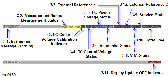
The instrument status bar displays the status of the entire instrument.
Instrument Status Bar
Displays instrument messages and warnings. Instrument messages are displayed in gray and warnings in red. For the meanings of the instrument messages and warnings, see Troubleshooting.
Displays the measurement status of E5052B.
|
Value |
Description |
|
Hold |
Measurement on hold (idling). |
|
Man |
The trigger source is set to "Manual" and waiting for trigger. |
|
Ext |
The trigger source is set to "External" and waiting for trigger. |
|
Bus |
The trigger source is set to "Bus" and waiting for trigger. |
|
NVideo |
The trigger source is set to "Narrow Video" for transient measurement only and waiting for trigger. |
|
N2Video |
The trigger source is set to "Narrow2 Video" for transient measurement only and waiting for trigger. |
|
WVideo |
The trigger source is set to "Wide Video" for transient measurement only and waiting for trigger. |
|
Meas |
A measurement is in progress. |
When DC Control Voltage Calibration is enabled, it is displayed in blue. When disabled, it is displayed in gray.
When the DC control voltage signal output is turned on, the specified voltage is displayed.
When the DC power voltage signal output is turned on, the specified voltage is displayed.
The specified attenuator value is displayed.
When the frequency reference signal is input to the External Reference Signal Input Connector (Ref In1) on the rear panel and the measurement signal of the E5052B is phase-locked to the reference signal, ExtRef1 is displayed in blue. The Ref In1 port is available in the phase noise measurement, segment phase noise measurement and transient measurement (narrow-narrow mode).
|
Value |
Description |
|
ExtRef1 displayed in blue |
Measurement signal is phase-locked to external reference signal. |
|
ExtRef1 displayed in gray |
Measurement signal is not phase-locked to external reference signal. |
In the phase noise measurement and segment phase noise measurement, the external reference signal can be used, when the “Ref. Osc.1 Source” function is set to “External”.
When Narrow-Narrow mode in the transient measurement is selected, this connector should be connected with the Ref Out connector. The error message of "291 Ref In 1 input not detected" is displayed when the clock signal is not input into this connector.
When the phase lock function is not operated properly, Unlock is displayed in red. Even when High Stability Frequency Reference Output Connector (Ref Oven)and External Reference Signal Input Connector (Ref In) are interconnected, the measurement signal may not be phase-locked immediately after powered on under a cool-temperature environment (i.e. the display of “ExtRef1” does not change from gray to blue). In this case, wait a few minutes until the instrument warms-up and “ExtRef1” is displayed in blue.
Displays the state of the execution of the VBA program in the E5052B.
|
Value |
Description |
|
Run |
VBA program is still running |
|
Stop |
VBA program has stopped |
Indicates the service mode status.
|
Value |
Description |
|
SVC (displayed in red) |
An abnormal condition has been detected inside the E5052B. The unit may be damaged. Notify the Customer Contact listed at the end of this brochure or the distributor from whom the unit was purchased. |
|
SVC (displayed in gray) |
The E5052B is in normal mode. |
Displays the date and time generated by the internal clock. The display format is as follows:
YYYY-MM-DD HH:MM
Where:
YYYY: Year (AD)
MM: Month
DD: Day
HH: MM: Time (0:00 to 23:59)
You can turn the date and time display on/off by: System > Misc Setup > Clock Setup > Show Clock.
When updating of information displayed on the LCD screen is turned off, this indicator is displayed.
When the frequency reference signal is input to the External Reference Signal Input Connector (Ref In2) on the rear panel and the measurement signal of the E5052B is phase-locked to the reference signal, ExtRef2 is displayed in blue. The Ref In2 port is available in all measurement functions of E5052B.
|
Value |
Description |
|
ExtRef2 displayed in blue |
Measurement signal is phase-locked to external reference signal. |
|
ExtRef2 displayed in gray |
Measurement signal is not phase-locked to external reference signal. |
In the phase noise measurement and segment phase noise measurement, the external reference signal can be used when the “Ref. Osc.2 Source” function is set to “External”. In other measurement functions, the external reference signal can be used without any setting.