How to start the Pulse Setup dialog
Using Hardkey/SoftTab/Softkey
Using a mouse
Press Sweep > Source Control > Pulse Setup....
Click Stimulus
Select Sweep
Select Sweep Control
Select Pulse Setup...
![]()
The Pulse Setup dialogs are available in the Standard Class if the S96325B Pulsed-RF measurements is installed.
External pulse generators can be used along with the VNA internal pulse generators. Learn more.
In this topic
Configure and Use External Pulse Generators
How to start the Pulse Setup dialog |
|
Using Hardkey/SoftTab/Softkey |
Using a mouse |
|
|
|
|
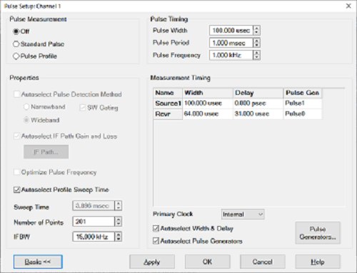
The Basic controls allow simple pulse measurements using the default (Autoselect) settings in the Advanced section of the dialog. Several VNA measurement settings are controlled by the Pulse setup, such as sweep type, number of points, and so forth. Pulse MeasurementOff - Source and Receivers are NOT pulsed Standard Pulse - With pulsed RF, the VNA can be configured to sweep in frequency, power sweep, and CW time.
Pulse Profile - Pulse profile measurements provides a time domain (CW frequency) view of the pulse envelope. Profiling is performed using a measurement technique that "walks" a narrow receiver "snapshot" across the width of the pulse. This is analogous to using a camera to take many small snapshots of a wide image, then piecing them together to form a single, panoramic view.
Pulse Profile measurement using default settings and R1 receiver.
Pulse TimingPulse Width - Sets the width of the source pulse. See measurement timing to learn how to control the receiver width and delay. Pulse Period The time to make one complete pulse. Pulse Frequency (PRF) The reciprocal of Period (1/ Period). See Internal Pulse Generators to learn more. By default, these settings configure Pulse Gen 1 to drive Source Modulators 1 and 2. This can be changed from the Advanced Settings Pulse Generator Setup dialog. -------- Advanced Settings ----------The following settings allow maximum control of a Pulse measurement. PropertiesAutoselect pulse detection method - . In Standard Pulse:
In Pulse Profile:
Autoselect IF Path Gain and Loss - For future use. Optimize Pulse Frequency - Automatically selects the Pulse Frequency and Pulse Period. Autoselect Profile Sweep Time - In Pulse Profile mode, adjusts the default X-axis start time to zero and the stop time double the Pulse Width. This allows you to see one complete pulse. If unchecked, the Sweep Time will not be changed. To adjust the X-axis manually, click OK to close the dialog. Then press Sweep > Main, then change the Start Time and Stop Time. Sweep Time - Sets the time the analyzer takes to complete one sweep. Number of Points - Sets the number of data points for the measurement. IFBW - Select the IFBW for the measurement.
Measurement TimingPort n, Rcvr - Used as RF Source Modulation Drive.
The Primary Clock is controlled by the internal or external pulse generator and is the primary pulse clock. The Internal and External selections are not the same as the Trigger Source Internal and External selections found in the Pulse Trigger tab of the Trigger dialog. However, they are inter-related as follows:
Autoselect Width and Delay - When checked, for Wideband mode and Pulse Gen = Pulse Trigger, the default setting for the receiver is adjusted to approximately 75% of the source pulse width, with 20% delay. This leaves approximately 5% of the source pulse ON after acquisition is complete. Autoselect Pulse Generators - When checked:
Pulse Generators... Click to launch the Pulse Generators Setup dialog.
|
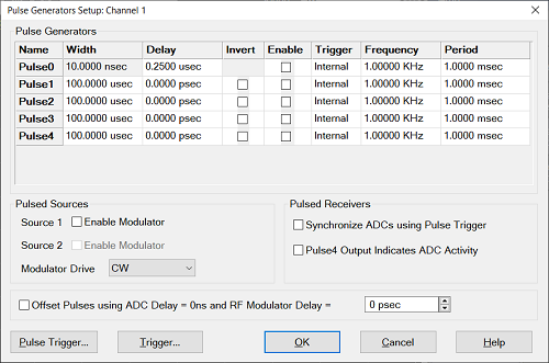
This dialog is available with Option S96325B (pulse generators). To see this dialog, press Pulse Generators... on the Pulse Setup dialog. Pulse GeneratorsConfigure the Pulse Generators to be used for your measurement. The pulse 0 is for the receiver. The pulse 1 is for source and P1 output and pulse 2 to 4 are for P2 to P4 output signal, receptively.
Important: If D + W is greater than P, then undefined VNA behavior results. There is NO error message or warning. Invert Check to cause the pulse ON time to be active low and OFF be active high. Enable Check to enable individual pulse generators. Trigger Choose from: (When ONE of these is changed, they ALL change. The internal Pulse Generators can NOT be triggered individually).
Frequency - Set the pulse frequency of each generator.
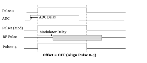
Period - Set the period of each generator. Learn more about the Pulse Generators. Pulsed SourcesCheck to enable the required internal source ports. Modulator Drive - Choose the pulse generator to modulate the specified source. Choose from CW (NO pulse), Pulse 1, 2, 3, 4, External. Offset PulsesOffset Pulses using ADC Delay Check Box
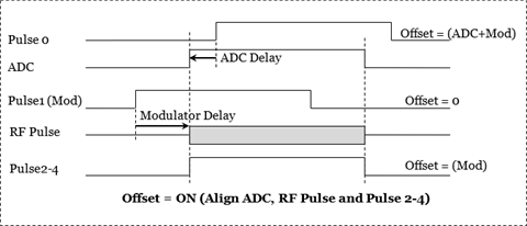
Offset Pulse Example Assume Pulse1 is used to modulate the RF signal, all Pulse outputs are enabled, all are set to zero delay, and all are set to the same width. The first timing diagram below is with offsets off and the second timing diagram is with offsets on.
Pulsed ReceiversSynchronize ADCs using Pulse Trigger - Check to enable triggering used to gate the ADC for wideband receiver measurements. This is the same as Pulse0 Enable. The Width can NOT be configured. Pulse4 Output Indicates - Check to use an oscilloscope connected to the pulse 4 to display when the ADC is making measurements. There are two selections: All ADC Activity - When selected, all ADC activity can be monitored, including ADC activity that may not be displayed on a trace. An example is background measurements that are used for receiver leveling, but are not actually displayed on a trace. Trace ADC Activity - When selected, Pulse4 will be active only during measurements that will be displayed on a trace. Pulse Trigger.. - Click to start the Pulse Trigger dialog. Trigger... - Accesses the Trigger dialog for setting up triggering. Learn more.
|
|
To see this dialog, press Pulse Trigger on the Pulse Generator Setup dialog or select Stimulus, then Trigger from the VNA Menu. Trigger SourceSelect Internal or External to provide sync capability for the internal pulse generators.
. Trigger Level/EdgeSets the edge of the trigger signal to which the internal pulse generators will respond when being externally triggered at the PulseSyncIn pin. . Positive = rising edge; Negative = falling edge. Receiver synchronizationSynchronize ADCs using pulse trigger - Check to enable triggering used to gate the ADC for wideband receiver measurements. The Width can NOT be configured. ADC trigger delay - Set the amount of time to wait before triggering the ADC to begin acquisition.
|
Using External Pulse Generators
Setup the External Pulse Generator as an External Device.
To perform a calibration in pulse mode, first configure and apply the pulse parameters (PRF, Pulse Width, Delays, IF gating, and so forth) before calibrating the system. This will ensure the VNA is configured properly during the calibration and measurement.