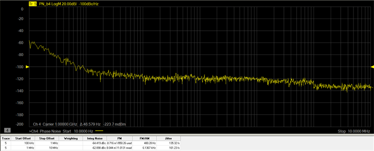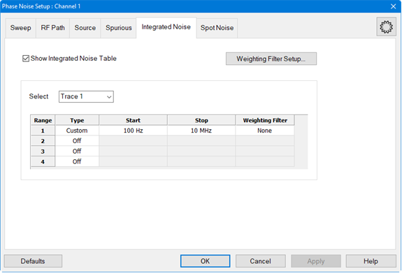
Integrated noise is the single sideband phase noise integrated over a measurement bandwidth from a start/stop offset frequency. Up to four offset frequency ranges can be defined.

In this topic:
When the Phase Noise Measurement Class is selected and a Phase Noise channel is created, the default measurement parameter is PN.
In the Integrated Noise tab, click on the Select drop down menu and select New Traces....
In the New Trace dialog, select PN.

The following procedure describes how to set up multiple measurement ranges.
In the Integrated Noise tab, click on the Select drop down menu and select the desired trace.
Click in the Type column for Range 1, click on the down arrow, then select Custom.
In the Start column for the range, set the frequency by either using the up/down arrows or by double-clicking in the data entry field and entering the frequency using the displayed keypad.
In the Stop column for the range, set the frequency by either using the up/down arrows or by double-clicking in the data entry field and entering the frequency using the displayed keypad.
Repeat steps 2 through 4 to add more ranges (up to four ranges).
If Weighting Filter files have been set up and saved, click in the Weighting Filter column for a range, click on the down arrow, then select the file. See below for a procedure on how to set up a Weighting Filter file.

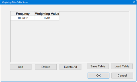
The weighting filter allows weighting values to be entered at specified frequencies. The weighting filters compensate external effects that affect the phase noise in the specified frequency ranges. When the weighting filters are applied, the trace data are corrected by the filter characteristics before the calculation of integrated noise.
In the Integrated Noise tab, click on the Weighting Filter Setup... button.
Click on the Add button.
In the Frequency column, set the frequency by either using the up/down arrows or by double-clicking in the data entry field and entering the frequency using the displayed keypad.
In the Weighting Value column, set the value by either using the up/down arrows or by double-clicking in the data entry field and entering the value using the displayed keypad.
Repeat steps 2 through 4 to add more weighting values.
Click on the Save Table button to save the settings to a file (.csv).
The Integrated Noise Table can be displayed below the trace area of the display showing trace number, start/stop offset, weighting filename (if used) integrated noise, phase modulation measured in degrees and radians, residual FM (Hz) or residual AM (%), and jitter. Residual FM (Hz) will be displayed when the PN Phase Noise measurement parameter is selected; residual AM (%) will be displayed when the AM Phase Noise measurement parameter is selected.

In the Integrated Noise tab, check Show Integrated Noise Table.
Integral Phase Noise: 10 x log (integ(10^ (L(f) /10 ))) [dBc]
Jitter (RMS Jitter): RMS Noise / (2 x f x pai x Carrier frequency) [sec]
RMS Noise: sqrt (2 x 10 ^ (Integral Phase Noise / 10) [rad]
Residual FM: sqrt (2 x integ (f ^2 x 10 ^ (L(f) /10 ))) [Hz]
Where,L(f): Phase Noise [dBc/Hz] and integ(x): Integral