Scale
The Scale, Reference Level and Reference Position settings (along with
Format) determine how the data trace appears
on the VNA screen.
See other 'Setup
Measurements' topics
Scale, Reference
Level and Position
The Scale, Reference Level and Reference Position settings (along with
format) determine how the data trace appears on the VNA screen.
How
to set Scale, Reference Level, and Position |
Using Hardkey/SoftTab/Softkey |
Using a mouse |
Press Scale
> Main > Scale / Reference
Level / Reference Position. Input the desired value. |
Right-click
on Y-axis annotation
or the trace status
label above the grid box. Select . |

|
Scale
dialog box help |
Note: The
scale settings are set to couple with other traces in each window.
The following settings assume that Scale Coupling is set to OFF.
Learn more about Scale Coupling.
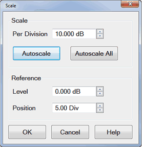
Scale
Per Division
Sets the value of the vertical divisions of a rectangular
display format. In Polar and Smith Chart formats, scale sets the
value of the outer circumference. Range: 0.001dB/div to 500 dB/div.
Tip:
Click on the Y-axis labels, then use a mouse scroll wheel to change
scale in preset increments. Or Right-click on Y-axis
annotation to change Scale.
Autoscale
- Automatically sets value of the vertical divisions and reference
value to fit the ACTIVE data trace within the grid area of the
screen. The stimulus values and reference position are not affected.
The analyzer
determines the smallest possible scale factor that will allow
all the displayed data to fit onto 80 percent of the vertical
grid.
The reference value is chosen to center
the trace on the screen.
Tip:
Double click on the Y-axis labels to autoscale the active trace.
Autoscale
All Automatically scales ALL data traces in the ACTIVE
WINDOW to fit vertically within the grid area of the screen.
Reference
Level
In rectangular formats, sets the value of the reference
line, denoted by  on
the screen. Range: -500 dB to 500 dB. on
the screen. Range: -500 dB to 500 dB.
In Polar and Smith chart formats, reference
level is not applicable.
Tip:
Click on the Y-axis labels, then drag up or down to change the
reference level in preset increments.
Position In rectangular formats,
sets the position of the reference line. Zero is the bottom line
of the screen and ten is the top line. Default position is five
(middle).
In Polar and Smith chart formats, reference
position is not applicable.
Tip:
Click on the triangle ,
then drag up or down to change the reference position in preset
increments. |
Scale Coupling
With Scale Coupling enabled, traces that have the same format will have
the same Scale, Reference Level, and Reference Position. You can choose
to couple the scale of traces that are in the same window, couple the
scale of all traces in all windows, or to have NO coupling.
How
to set Scale Coupling |
Using Hardkey/SoftTab/Softkey |
Using a mouse |
Press Scale
> Main > Scale Coupling.... |
Right-click
on Y-axis annotation. Select . |
|
Scale
Coupling dialog box help |
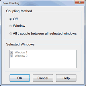
Allows traces that share the same format
to have the same Scale,
Reference Level and Reference
Position.
Coupling Method
Off
- No coupling. Traces are scaled individually. Default setting.
Window
- All traces with the same format in each selected window share
the same scale settings.
All
- All traces in ALL selected windows with the same format share
the same scale settings.
When Window
or All coupling is
enabled, the scale settings for the active trace are assumed
by other coupled traces with the same format. When there are traces with a different format
present, all traces with that format assume the trace settings
of the lowest-numbered trace of that format. Once enabled, scale settings for all coupled
traces with the same format can be changed with any coupled
trace being active.
Selected Windows
Available when either the Window
or All method is selected.
Selected windows will participate in scale coupling. All windows
are selected by default. Clear a checkbox to 'Opt-out' of scale
coupling for that window.
About Autoscale and Scale
Coupling
Autoscale
(not Autoscale All) affects the active trace in the active
window. All traces that are coupled to this trace assume
the new scale settings of the active trace. This could
cause some traces to NOT show on the screen.
Autoscale
All with Coupling Method...
Off - All traces
in the active window are autoscaled independently. Window - All traces
in each selected window are autoscaled to fit within
a common set of scaling factors. All - All traces
in all selected windows are autoscaled to fit within
a common set of scaling factors. |
|
Y-Axis Graph (Lin/Log Scale),
Top, Bottom, Ref X/Y Level, Ref X/Y Position
How
to set Y-Axis Spacing |
Using Hardkey/SoftTab/Softkey |
Press Scale
> Main > Y-Axis Spacing / Top / Bottom / Ref
Y Level / Ref Y Position / Ref X Level / Ref X Position. |
|
Y Axis Spacing - Selects either
a linear or log scale Y-axis format.
Top - Sets the maximum scale
value for the Log Y-axis.
Bottom - Sets the minimum scale
value for the Log Y-axis.
Ref Y Level - Sets the Y axis
Reference Level of the specified trace in the specified window.
Ref Y Position - Sets the Y
axis Reference Position of the specified trace in the specified window.
Ref X Level - Sets the X axis
Reference Level of the specified trace in the specified window.
Ref X Position - Sets the X
axis Reference Position of the specified trace in the specified window.
Graph Area Graticules
In the graph area, multiple
traces can be drawn overlaid. Different graticule is drawn based on the
active trace.
The following is an example of a case that these 3 traces are shown:
Trace 1 = Log ( 10k to 1M )
Trace 2 = Log ( 5k to 500k )
Trace 3 = Linear
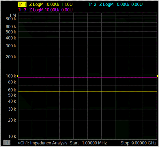
When trace 1 is active.
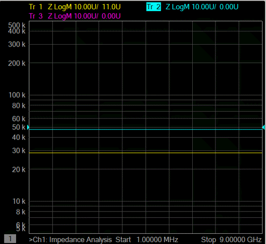
When
Trace 2 is active (graticule is still log, but different from Trace 1)
When
Trace 3 is active.
Magnitude Offset
Magnitude Offset allows you to offset the magnitude (not phase) data
by a fixed and / or sloped value in dB. If the display format is Linear
Magnitude or Real (unitless), the conversion from dB is performed and
the correct amount of offset is implemented.
How
to set Magnitude Offset |
Using Hardkey/SoftTab/Softkey |
Press Scale
> Constants >
Mag Offset / Mag Slope. |
|
Magnitude Offset dialog box
help |
Magnitude
Offset allows you to offset the magnitude (not phase) data by
a fixed and / or sloped value in dB. If the display format is
Linear Magnitude or Real (unitless), the conversion from dB is
performed and the correct amount of offset is implemented.
The Magnitude offset setting affects
only the active trace.
Mag Offset Offsets
the entire data trace
by the specified value.
Mag Slope Offsets
the data trace by a value that changes with frequency. The offset
slope begins at 0 Hz.
For your convenience, the offset value at the start frequency
is calculated and displayed.
|