Other topics about Advanced Calibration
In most measurements, the user can use pre-defined calibration kits as they are. However, it may be necessary to change the definition of a calibration kit (or create a new one) when changing the pre-defined connector between male and female (e.g. from OPEN (f) to OPEN (m)) or when a special standard is used or a high degree of accuracy is demanded. When it is necessary to change the definition of a calibration kit that contains a calibration device but no calibration kit model, the user must fully understand error correction and the system error model.
A user-defined calibration kit may be used in the following circumstances:
When the user wants to use connectors other than those pre-defined in the calibration kits for the E5061B (e.g., a SMA connector).
When the user wants to use different standards in place with one or more standards pre-defined in the E5061B. For example, when three offset SHORT standards are used instead of OPEN, SHORT, and LOAD standards.
When the user wants to modify the standard model of a pre-defined calibration kit and turn it into a more accurate model. It is possible to perform better calibration if the performance of the actual standard is better reflected in the standard model. For example, you may need to define the 7-mm LOAD standard as 50.4 Ω instead of 50.0 Ω.
The terms used in this section are defined as follows:
An accurate physical device, for which the model is clearly defined, used to determine system errors. With the E5061B, the user may define up to 21 standards per calibration kit. Each standard is numbered from 1 to 21. For example, standard 1 for the 85033E 3.5-mm calibration kit is a SHORT standard.
The type of standard used to classify a standard model based on its form and construction. Five standard types are available: SHORT, OPEN, LOAD, delay/THRU, and arbitrary impedance.
The numeric characteristics of the standard used in the selected model. For example, the offset delay (32 ps) of the SHORT standard in the 3.5-mm calibration kit is a standard coefficient.
A group of standards are used in a calibration process. Class allows you to use the different standard for each port. For each class, the user must select the standards to use from the available standards.
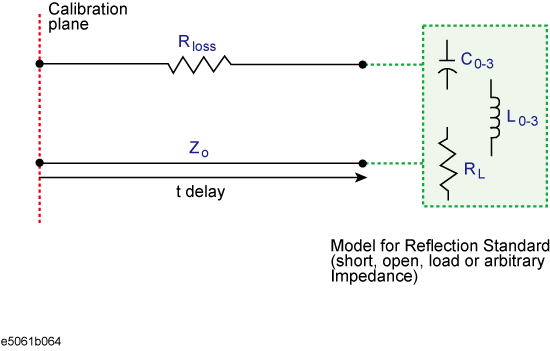
The following figures show the parameters used in defining the standards.
Reflection Standard Model (SHORT, OPEN, or LOAD)
Transmission Standard Model (THRU)
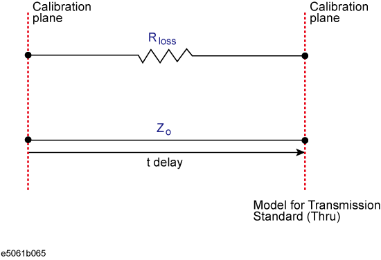
The offset impedance between the standard to be defined and the actual measurement plane. Normally, this is set to the system's characteristic impedance.
The delay that occurs depending on the length of the transmission line between the standard to be defined and the actual measurement plane. In an OPEN, SHORT, or LOAD standard, the delay is defined as one-way propagation time (sec.) from the measurement plane to the standard. In a THRU standard, it is defined as one-way propagation time (sec.) from one measurement plane to the other. The delay can be determined through measurement or by dividing the exact physical length of the standard by the velocity coefficient.
This is used to determine the energy loss caused by the skin effect along the length (one-way) of the coaxial cable. Loss is defined using the unit of ohm/s at 1 GHz. In many applications, using the value 0 for the loss should not result in significant error. The loss of a standard is determined by measuring the delay (sec.) and the loss at 1 GHz and then substituting them in the formula below.

It is extremely rare for an OPEN standard to have perfect reflection characteristics at high frequencies. This is because the fringe capacitance of the standard causes a phase shift that varies along with the frequency. For internal calculation of the analyzer, an OPEN capacitance model is used. This model is described as a function of frequency, which is a polynomial of the third degree. Coefficients in the polynomial may be defined by the user. The formula for the capacitance model is shown below:
![]()
F: measurement frequency
C0 unit: (Farads) (constant in the polynomial)
C1 unit: (Farads/Hz)
C2 unit: (Farads/Hz2)
C3 unit: (Farads/Hz3)
It is extremely rare for a SHORT standard to have perfect reflection characteristics at high frequencies. This is because the residual inductance of the standard causes a phase shift that varies along with the frequency. It is not possible to eliminate this effect. For internal calculation of the analyzer, a short-circuit inductance model is used. This model is described as a function of frequency, which is a polynomial of the third degree. Coefficients in the polynomial may be defined by the user. The formula for the inductance model is shown below:
![]()
F: Measurement frequency
L0 unit: [Henry] (the constant in the polynomial)
L1 unit: [Henry/Hz]
L2 unit: [Henry/Hz2]
L3 unit: [Henry/Hz3]
In most existing calibration kits, THRU standards are defined as "zero-length THRU," i.e., the delay and loss are both "0". Such THRU standard does not exist, however, calibration must be done with two test ports interconnected directly.
The measurement accuracy depends on the conformity of the calibration standard to its definition. If the calibration standard has been damaged or worn out, the accuracy will decrease.
This section provides the procedure to change the definition of a calibration kit.
Press Cal > Cal Kit, then select the calibration kit to be redefined.
Click Modify Kit.
If necessary ,click Label Kit and type a new label for the calibration kit.
Click Define STDs and select the standard number to be redefined.
If necessary, click Label, then type your desired name for the selected standard.
Click STD Type, then select the type of standard.
Set the standard coefficient.
Repeat steps 4 to 7 to redefine all standards for which changes are necessary, then click Return.
Click Specify CLSs, then select the class.
Select the test port. Select Set All to use the same standard for all test ports.
Select the standards to be registered in the class from the standard number to be redefined. Define classes for all test ports that need to be redefined, then click Return.
Repeat the steps 9 to 12 to redefine all classes that need to be modified, then click Return.
Press Cal key.
Click Cal Kit, then select a calibration kit.
Click Modify Cal Kit > Restore Cal Kit to preset the selected kit definition at the factory setting.