This section introduces an example of how to measurement loop stability for low-frequency amplifier.
In this example, the DUT is evaluated by following the steps.
|
Step |
Description |
|
Set the measurement conditions. |
|
|
Execute calibration. |
|
|
Connect the DUT. |
|
|
4. Scaling |
Adjust the scale to confirm the result of measurement. |
The measurement conditions are defined by following the steps described below.
|
Setup Description |
Key Operation |
|
Presetting |
Preset > OK |
|
Setting trace number: 2 |
Display > Num of Traces > 2 > Allocate Traces > x2 |
|
Specifies measurement port: Gain-Phase |
Meas > Measurement Port > Gain-Phase
|
|
Specifies impedance of receiver port: 1 MΩ |
Meas > Gain-Phase Setup > T Input Z > 1 MΩ |
|
Specifies attenuator of receiver port: 20 dB |
Meas > Gain-Phase Setup > T Attenuator > 20 dB |
|
Data format: Tr1:LogMag Tr2:Phase |
(Tr1) Format > Log Mag |
|
Sweep type: Log Frequency |
Sweep Setup > Sweep Type > Log Freq |
|
Start frequency: 100 Hz |
Start > 1 > 0 > 0 > x1 |
|
Stop frequency: 1 MHz |
Stop > 1 > M/u |
|
IF bandwidth auto: ON |
Avg > IFBW Auto (Turn it ON.) |
|
IF bandwidth auto limit: 100 Hz |
Avg > IFBW Auto Limit > 1 > 0 > 0 > x1 |
|
Power: -20 dBm |
Sweep Setup > Power > Power > +/- > 2 > 0 > x1 |
The THRU response calibration (Gain-Phase) is executed.
|
Setup Description |
Key Operation or Connecting Operation |
|
Connect THRU connection |
Connect THRU connection. |
|
Executing the THRU response |
Cal > Calibrate > Response (Thru) > Thru > Done |
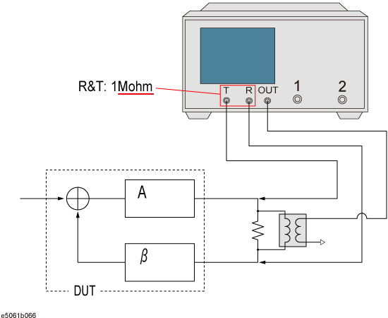
Connect the DUT as shown below.
Set each parameter for the scale setting. It is necessary to specify the trace pressing the Trace Next or Trace Prev before each parameter is specified. The following table is example of setting.
|
Setup Description |
Key Operation |
|
Scale divisions: 10 |
(Tr1) Scale > Divisions > 1 > 0 > x1 |
|
Scale/Div: 10 dB/div (Tr1), 45 °/div (Tr2) |
(Tr1) Scale > Scale/Div > 1 > 0 > x1 |
|
Reference position: 5 Div |
(Tr1) Scale > Reference Position > 5 > x1 |
|
Reference value: 0 dB (Tr1), 0 °/div (Tr2) |
(Tr1) Scale > Reference Value > 0 > x1 |
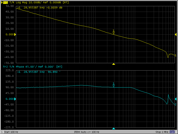
Example of the loop gain stability measurement screen