This section describes the following functions that can be used to improve phase measurement accuracy.
Other topics about Optimizing Measurements
Electrical Delay is a function that adds or removes a pseudo-lossless transmission line with a variable length corresponding to the receiver input. Using this function enables you to improve the resolution in phase measurement and thereby measure the deviation from the linear phase. You can specify the electrical delay trace by trace.
Press Channel Next (or Channel Prev) and Trace Next (or Trace prev) to activate the phase trace of which you want to specify the electrical delay.
Press Scale > Electrical Delay.
Change the electrical delay (in seconds) in the data entry area.
For how to determine the deviation from a linear phase, see Measuring the Deviation from a Linear Phase.
Press Channel Next (or Channel Prev) and Trace Next (or Trace prev) to activate the trace of which you want to set the electrical delay.
Place the active marker in an appropriate position.
Press Maker Fctn.
Click Marker -> Delay to set the electrical delay to the group delay value at the position of the active marker (a value smoothed with the aperture of 20% regardless of the smoothing setting).
Phase offset is a function used to add or subtract a predetermined value relative to the frequency to and from the trace. Using this function enables you to simulate the phase offset which occurs as a result of, say, adding a cable.
The phase offset can be specified from -360° to +360° .
Press Channel Next (or Channel Prev) and Trace Next (or Trace prev) to activate the trace of which you want to specify the phase offset.
Press Scale > Phase Offset, then enter the phase offset (° ) in the data entry area.
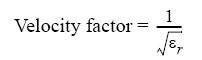
The velocity factor is the ratio of the propagation velocity of a signal in a coaxial cable to the propagation velocity of that signal in free space. The velocity factor for a common cable is about 0.66. The propagation velocity depends on the dielectric constant (εr) of the dielectric substance the cable.
By specifying the velocity factor, you can match the equivalent length (in meters) appearing in the data entry area to the actual physical length when using the Electrical Delay or Setting port extensions to specify the electrical delay (in seconds).
You can define the velocity factor channel by channel.
Press Channel Next (or Channel Prev) to activate the channel for which you want to specify the velocity factor.
Press Cal > Velocity Factor, then the velocity factor in the data entry area.
Port Extension is a function for moving the calibration reference plane by specifying the electrical delay. This function is useful, for example, when you cannot directly perform calibration at the DUT terminal because the DUT is inside the test fixture. In such a case, this function enables you to first perform calibration at the test fixture terminal and then move the calibration plane to the DUT terminal by extending the port.
Port extension corrects the electrical delay of each test port (phase shift) only. It cannot remove errors caused by the loss in and incorrect matching of cables, adapters, or test fixtures.
In addition to port extension, you can set loss values for each port. By correcting loss due to port extension, more accurate measurement results are obtained.
There are two types of loss value settings: loss values at two frequency points for a specified port, and a DC loss value. You can make these settings at the same time for each port.
The port extension is not available for the Gain-Phase measurement.
You can set loss values channel by channel. Setting loss values for one particular channel does not affect other channels.
You can define port extension channel by channel. Setting port extension for one particular channel does not affect other channels.
Press Channel Next (or Channel Prev) to activate the channel for which you want to enable port extension.
Press Cal > Port Extensions.
Turn ON Extensions.
Follow the steps below to set the delay for coaxial cable:
Press Channel Next (or Channel Prev) to activate the channel for which you want to set port extension.
Press Cal > Port Extensions.
Click Extension Port 1 or Extension Port 2 to select the port.
Click Extension to set the extension in sec.
Press Channel Next (or Channel Prev) to activate the channel for which you want to set loss values.
Press Cal > Port Extensions.
Click Extension Port 1 or Extension Port 2 to select the port.
Click Loss to set a loss value.
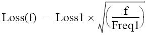
Click Loss1 [OFF] to toggle to Loss1 [ON] (enabled), and enter a loss value (Loss1) and a frequency (Freq1).
If you want to set loss at two frequency points, press Loss2 [OFF] to toggle to Loss [ON] (enabled), and enter a loss value (Loss2) and a frequency (Freq2).
Expression to calculate loss using Loss 1:
Expression to calculate loss using Loss 1 and Loss 2:
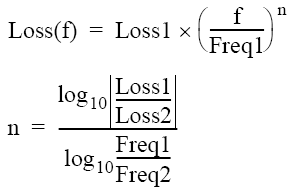
When you specify two frequency points, set the lower frequency to Loss1, and the higher one to Loss2.
Click Cal > Port Extensions > Extension Port 1 or Extension Port 2 to select the port.
Click Loss > Loss1 [OFF] to toggle to Loss1 [ON] (enabled).
Click Loss at DC, then enter a DC loss value.
The auto port extension function measures port extension and loss values for each port using the OPEN/SHORT standard connected to the port, automatically calculates and sets them.
When the auto port extension function is completed, the port extensions and loss values are updated to the calculated values.
You can use both open and short measurement values in the auto port extension function. Note that in this case, the average value of the calculation results is used for updating.
You can set the auto port extension function channel by channel. Setting the auto port extension function for one particular channel does not affect other channels.
When the sweep type is power sweep, the auto port extension is not available.
Select the port(s) of which you want to use the auto port extension function.
Press Channel Next (or Channel Prev) to activate the channel of which you want to set auto port extension.
Press Cal > Port Extensions > Auto Port Extension > Select Ports to select the port(s) of which you want to use the auto port extension function.
Set the frequency points ofh which you want to calculate a loss value.
Press Cal > Port Extensions > Auto Port Extension > Select Ports > Method to set the frequencies used for calculation.
If you have selected User Span, use User Span Start and User Span Stop to set a start value and a stop value.
For Current Span and User Span, a frequency point at 1/4 of the frequency range is set to Freq1; a frequency point at 3/4 of the frequency range is set to Freq2.
If the setting is not made before starting OPEN/SHORT standard measurement, it does not affect the calculation result.
Specify whether you want to include a loss value in the calculation result.
Press Cal > Port Extensions > Auto Port Extension > Select Ports > Include Loss to turn it ON.
If the setting is not made before starting the measurement of the OPEN/SHORT standard, it does not affect the calculation result.
Specify whether you want to include a DC loss value in the calculation result.
Press Cal > Port Extensions > Auto Port Extension > Adjust Mismatch to turn it ON.
If the setting is not made before starting the measurement of the OPEN/SHORT standard, it does not affect the calculation result.
Calculate port extensions and loss values based on the calculation results using the OPEN/SHORT standard.
Press Cal > Port Extensions > Auto Port Extension.
If you use the OPEN standard, click Measure OPEN, and select the port(s) of which you want to execute measurement. Execution is restricted to ports selected in Selecting a port(s)
If you use the SHORT standard, click Measure SHORT, and select the port(s) of which you want to execute measurement. Execution is restricted to ports selected in Selecting a port(s).
If a port extension value or loss value has been set, the value is updated to the calculated result.
If you execute both open measurement and short measurement, the average of the calculation results is reflected to the port extension and loss value.
When you exit from the softkey menu in the same level after open/short measurement, the measurement results are deleted. Note that you can use a GPIB command.
Port extension and loss values that have been calculated are not cleared.