The E5061B allows users to evaluate the DUT (device under test) characteristics by using the following measurement parameters.
Other topics about Setting Measurement Conditions
For each channel, the measurement should select either S-parameter or Gain-Phase. This function is available only in option 3L5/3L4/3L3 (Gain-Phase).
Press Meas > Measurement Port.
Select S-Parameter or Gain-Phase.
All traces in the selected channel are set to either S11 or T/R, respectively.
By using the commands, the parameters of S-parameters (Sxx) and Gain-Phase (T/R, T, R) can exist in one channel. The Measurement Port softkey has no equivalent SCPI command.
S-parameters (scattering parameters) are used to evaluate how signals are reflected by and transferred through the DUT. An S-parameter is defined by the ratio of two complex numbers and contains information on the magnitude and phase of the signal. S-parameters are typically expressed as follows:
Sout in
out: port number of the DUT from which the signal is output
in: port number of the DUT to which the signal is input
For example, S-parameter S21 is the ratio of the output signal of port 2 on the DUT with the input signal of port 1 on the DUT, both expressed in complex numbers.
Press Channel Next (or Channel Prev) and Trace Next (or Trace Prev) to select the trace.
Select a softkey that corresponds to the desired measurement parameter. If the desired softkey is gray out, press Meas > Measurement Port > S-Parameter.
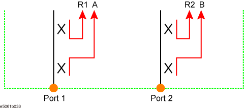
Absolute shows the absolute power for reference and received signals on the port.
|
Softkey |
Description |
|
A (n) |
Absolute measurement in Port 1, test receiver |
|
B (n) |
Absolute measurement in Port 2, test receiver |
|
R1 (n) |
Absolute measurement in Port 1, reference receiver |
|
R2 (n) |
Absolute measurement in Port 2, reference receiver |
where n in the parentheses is the stimulus port number. For example, R1(1) means the reference level while the signal is output from the port 1, and A(2) means the received signal level into port 1 while the signal is output from the port 2.
Press Channel Next (or Channel Prev) and Trace Next (or Trace Prev) to select the trace.
Press Meas > Absolute. If Absolute is gray out, press Meas > Measurement Port > S-Parameter.
Select a softkey that corresponds to the desired measurement parameter.
Press Channel Next (or Channel Prev) to select the channel.
Press Meas > Measurement Port > Gain-Phase.
Press Trace Next (or Trace Prev) to select the trace.
Press Meas > Gain-Phase. Then select a softkey that corresponds to the desired measurement parameter.
The input impedance can be selected from 50 Ω or 1 MΩ.
Press Channel Next (or Channel Prev) and Trace Next (or Trace Prev) to select the trace.
Press Meas > Gain-Phase Setup > Input Impedance > R Input Z (or T Input Z).
Select 50 Ω or 1 MΩ.
The input attenuator can be selected from 0 dB or 20 dB. When your input signal exceeds the signal over -5 dBm (50 Ω input) or 0.18 Vpeak (1 MΩ input), the attenuator should be set at 20 dB.
Press Channel Next (or Channel Prev) and Trace Next (or Trace Prev) to select the trace.
Press Meas > Gain-Phase Setup > Input Attenuator > R Attenuator (or T Attenuator).
Select 0 dB or 20 dB.