Other topics about Setting Measurement Conditions
The E5061B allows you to setup multiple channels to perform measurement under different stimulus conditions.
As multiple traces (measurement parameters) can be displayed for each channel, no feature is provided to link the stimulus conditions between channels, and each channel is always independent of the others. In other words, you need to set the measurement conditions and execute calibration for each channel you use for measurement.
When you set items whose setting target is channels/traces (refer to Parameter setting for each setup item), the target is the selected (active) channel/trace. You can specify only the displayed channels/traces as active channels/traces. Therefore, set the display of channels/traces before setting the measurement conditions.
The following table lists the setting parameters and indicates the setup item (analyzer, channel, or trace) that each parameter controls along with the applicable setup key(s).
|
Parameter |
Controlled Setup Items |
Setup Key(s) |
||
|
Analyzer |
Channel |
Trace |
||
|
Stimulus Settings |
|
|||
|
Sweep range |
|
x |
|
Start, Stop, Center, Span |
|
Power, CW frequency |
|
x |
|
Sweep Setup > Power |
|
Sweep time/Sweep delay time |
|
x |
|
Sweep Setup > Sweep Time, Sweep Delay |
|
Number of points |
|
x |
|
Sweep Setup > Points |
|
Segment sweep |
|
x
|
|
Sweep Setup > Sweep Type, Edit Segment Table, Segment Display |
|
DC Bias |
|
x |
|
Sweep Setup > Sweep Type |
|
Trigger Settings |
|
|||
|
Trigger mode |
|
x |
|
Trigger > Hold/Single/ Continuous |
|
|
x |
|
|
Hold All Channels/Continuous Disp Channels |
|
Trigger source, Trigger Event, Trigger Scope |
x |
|
|
Trigger > Trigger Source, Trigger Event, Trigger Scope |
|
Trigger |
x |
|
|
Trigger > Restart/Trigger |
|
Ext Trigger Input, Trigger Delay |
x |
|
|
Trigger > Ext Trig Input, Trigger Delay |
|
Ext Trigger Output, Polarity, Position, Pulse Width |
x |
|
|
Trigger > Ext Trig Output, Polarity, Position, Pulse Width |
|
Response Settings |
|
|||
|
Measurement parameter |
|
|
x |
Meas |
|
Data format |
|
|
x |
Format |
|
Scale, Electrical delay, Phase offset |
|
|
Scale
|
|
|
Memory trace and data math |
|
|
x |
Display > Display/Data-> Mem/ Data Math |
|
Equation Editor |
|
x |
|
Display > Equation Editor/Equation (ON/OFF) |
|
Window title |
|
x |
|
Display > Edit Title Label/ Title Label (ON/OFF) |
|
Graticule label in rectangular form |
|
x |
|
Display > Graticule Label (ON/OFF) |
|
Color inversion |
x |
|
|
Display > Invert Color |
|
Frequency display |
x |
|
|
Display > Frequency (ON/OFF) |
|
Display update |
x |
|
|
Display > Update (ON/OFF) |
|
Averaging |
|
x |
|
Avg > Averaging Restart/ Avg Factor/Averaging (ON/OFF) |
|
Averaging Trigger |
x |
|
|
Avg > Avg Trigger (ON/OFF) |
|
Smoothing |
|
|
x |
Avg > Smo Aperture/ Smoothing (ON/OFF) |
|
IF bandwidth, IF BW Auto, IF BW Auto Limit |
|
x |
|
Avg > IF Bandwidth, IFBW Auto, IFBW Auto Limit |
|
Calibration |
|
x |
|
Cal |
|
System Impedance |
x |
|
|
Cal > Set Z0 |
|
Marker |
|
|
Marker, Marker Search, Maker Fctn |
|
|
Market Table |
x |
|
|
Maker Fctn > Maker Table |
|
Analysis |
|
|||
|
Time domain, Fault Location, |
|
|
x |
Analysis > Gating, Fault Location |
|
SRL |
|
x |
|
Analysis > SRL |
|
Parameter conversion |
|
|
x |
Analysis > Conversion |
|
Limit test, Ripple Test, Bandwidth Test |
|
|
x |
Analysis > Limit Test, Ripple Test, Bandwidth Limit |
|
Saving and recalling data |
x |
|
|
Save/Recall |
|
Macro |
x |
|
|
Macro Setup, Macro Run, Macro Break |
|
System |
|
|||
|
Printing/Saving display Screen/Beeper/GPIB settings/Network Settings/Date & Time/Key Lock/Backlight/Firmware Revision/Service menu |
x |
|
|
System |
|
Preset |
x |
|
|
Preset |
The number of channels and the number of traces are 4. The maximum number of points is 1601.
The measurement result for each channel is displayed in its dedicated window (channel window). You cannot have a single window to display the measurement results from more than one channel. This means that the setting of the window layout determines the number of channels displayed on screen.
The execution of measurement for each channel does not depend on how the channel is displayed (channels that are not displayed can be measured). For information on executing measurement for each channel (trigger mode and trigger source), refer to Making Measurements.
The procedure for setting the window layout is as follows:
Press Display > Allocate Channels.
Press the desired softkey to select the window layout.
Depending on the measurement parameters of the traces displayed for each channel, the sweep necessary for each channel is executed. For more information, refer to Sweep Order in Each Channel.
You specify the trace display by setting the number of traces (upper limit of displayed trace numbers). For example, if you set the number of traces to 3, traces 1 through 3 are displayed.
The procedure for setting the number of traces is as follows:
Press Channel Next (or Channel Prev) to select the channel for which you want to set the number of traces.
Press Display > Number of Traces.
Press the desired softkey to set the number of traces.
Traces are laid out and displayed in the order of the trace number from graph 1 according to the graph layout in the channel window.
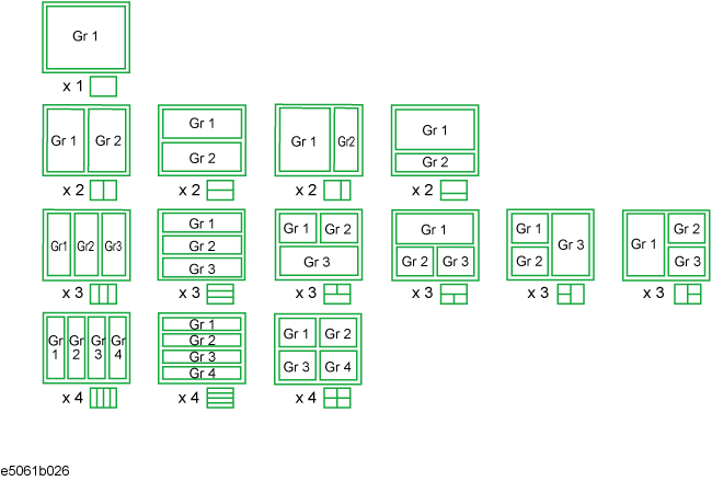
You can select the graph layout from the windows layout.
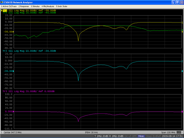
If the number of traces is less than the number of graphs, nothing is displayed in the remaining area. If the number of traces you set exceeds the number of graphs, excess traces are superimposed from the first graph. For example, if you select![]() as the graph layout and set the number of traces to 4, graph 1 (Gr1 in Graph layout) display traces 1 and 4, respectively, by superimposing, and graph 2 (Gr2 in Graph layout) and graph 3 (Gr3 in Graph layout) displays trace 2 and trace 3 as shown in the figure below.
as the graph layout and set the number of traces to 4, graph 1 (Gr1 in Graph layout) display traces 1 and 4, respectively, by superimposing, and graph 2 (Gr2 in Graph layout) and graph 3 (Gr3 in Graph layout) displays trace 2 and trace 3 as shown in the figure below.
The procedure for setting the graph layout is as follows:
Press Channel Next (or Channel Prev) to select the channel for which you want to set the graph layout.
Press Display > Allocate Traces.
Press the desired softkey to select the graph layout shown below.
The active channel is the one whose settings can currently be changed. The window frame of the active channel is displayed brighter than the window frames of the other channels. To change the settings specific to a certain channel, you must first activate the channel.
To change the active channel, use the following hardkeys:
|
Hardkey |
Function |
|
Channel Next |
Change the active channel to the next channel with the larger channel number. |
|
Channel Prev |
Change the active channel to the previous channel with the smaller channel number. |
The active trace is the one whose settings can currently be changed. The trace name on the screen (for example, Tr2) of the current active trace is highlighted and indicated with ![]() to the left. To change the settings specific to a certain trace, you must first activate the trace.
to the left. To change the settings specific to a certain trace, you must first activate the trace.
To select the active trace, use the following hardkeys:
|
Hardkey |
Function |
|
Trace Next |
Change the active trace to the next trace with the larger trace number. |
|
Trace Prev |
Change the active trace to the previous trace with the smaller trace number. |