Other topics about Fixture Simulator
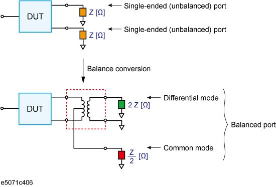
The balance-unbalance conversion function simulates a measurement under a balanced state based on measurement results obtained in an unbalanced state. This function enables you to evaluate devices with balanced ports.
Be sure to set the impedances of the two unbalanced ports equal to each other. For more details on setting up port impedance for unbalanced ports, refer to Converting the Port Impedance of the Measurement Result.
Balance-unbalance conversion

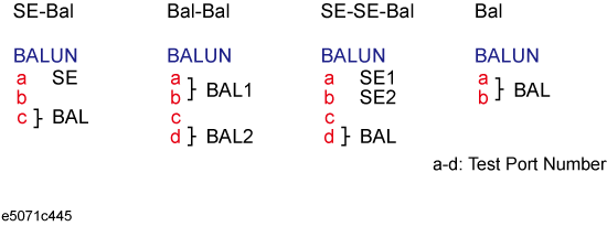
The types of devices that can be evaluated using the E5071C are shown below. To evaluate a balanced device, an E5071C with at least three test ports is required.
Types of balanced devices that can be evaluated with E5071C
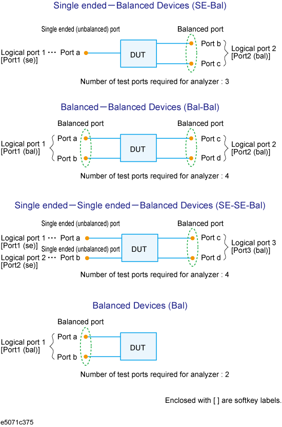
In the terminology of the E5071C, ports after the balance conversion are called logical ports (or DUT ports).
You can freely assign the test ports of the E5071C to logical ports (ports a to d in the figure above).
Turn on the balance-unbalance conversion function to measure the following parameters.
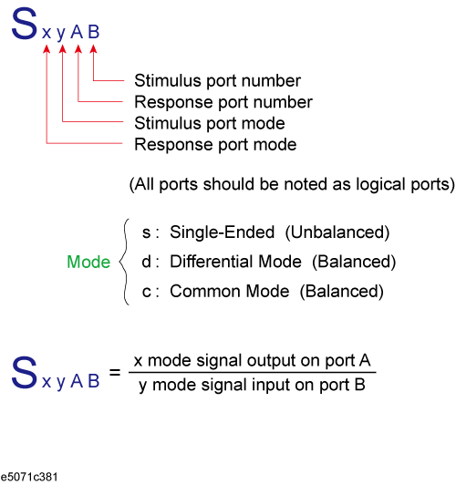
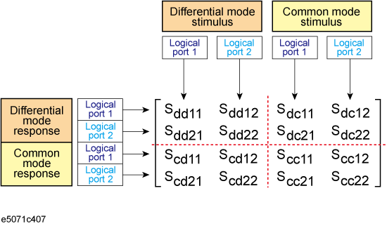
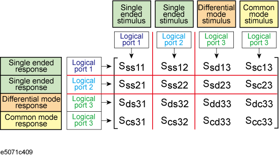
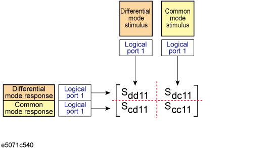
By turning on the balance-unbalance conversion function, you can obtain the S-parameter of the balanced port separately for two modes, the differential mode and the common mode. The following figure shows the notation of the S-parameter in balance measurement (mixed mode S-parameter).
Notation of mixed mode S-parameter
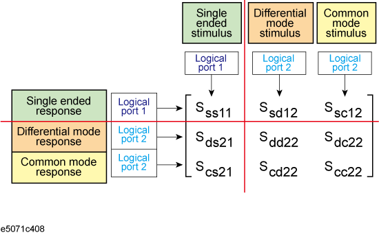
The following two figures show the mixed mode S-parameter when measuring each balanced device.
Mixed mode S-parameter when measuring a single-ended - balanced device
Mixed mode S-parameter when measuring a balanced - balanced device
Mixed mode S-parameter when measuring a single-ended - single-ended - balanced device
Mixed mode S-parameter when measuring a balanced device
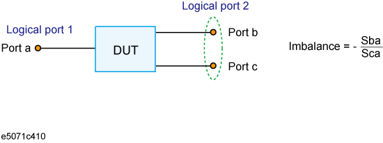
By turning on the balance-unbalance conversion function, you can select the imbalance parameter of the balanced port as the measurement parameter. The following three figures show the imbalance parameter you can select when measuring each balanced device.
Parameter when measuring a single-ended - balanced device (Imbalance)
Parameter when measuring a balanced - balanced device (Imbalance1, Imbalance2)
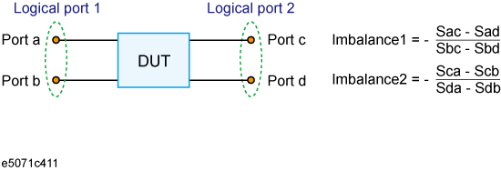
Parameter when measuring a single-ended - single-ended - balanced device (Imbalance1, Imbalance2, Imbalance3, Imbalance4)

The balance matching circuit (Differential matching circuit embedding) is not applied to single-ended S-parameter results. For example, the balance matching circuit is not applied to the imbalance parameter as it is derived from single-ended S-parameters.
By turning on the balance-unbalance conversion function, you can select CMRR (ratio between the transmission characteristic in the differential mode and that in the common mode) of the balanced port as the measurement parameter. The table below shows the CMRR parameter you can select when measuring each balanced device.
|
Device Type |
CMRR |
|
Single-ended - balanced device |
Sds21/Scs21 and Ssd12/Ssc12 |
|
Balanced - balanced device |
Sdd21/Scc21 |
|
Single-ended - single-ended - balanced device |
Sds31/Scs31 and Sds32/Scs32 |
When using three test ports, perform a full three-port calibration on the test ports to be used. When using four test ports, perform a full four-port calibration.
Extend the calibration plane, if necessary, by using the port extension function or network de-embedding function. For more on the port extension and network de-embedding functions, see Extending the Calibration Plane Using Network De-embedding.
Press Analysis key.
Click Fixture Simulator > Topology > Device.
Select the balanced/unbalanced topology.
|
Softkey |
Function |
|
SE-Bal |
Establishes port 1 on the DUT as an unbalanced port and port 2 as a balanced port |
|
Bal-Bal |
Establishes both port 1 and port 2 on the DUT as balanced ports |
|
SE-SE-Bal |
Establishes port 1 and port 2 on the DUT as unbalanced ports and port 3 as a balanced port |
|
Bal |
Establishes port 1 on the DUT as balanced ports |
Select each port on the analyzer to which a port on the DUT is connected.
When you have selected SE-Bal:
|
Softkey |
Function |
|
Port 1 (se) |
Selects a port on the analyzer from among 1, 2, 3, and 4 for connection to logical 1 (Port a) |
|
Port 2 (bal) |
Selects two ports on the analyzer from among 1-2, 1-3, 1-4, 2-1, 2-3, 2-4, 3-1, 3-2, 3-4, 4-1, 4-2, and 4-3 for connection to logical port 2 (Port b and Port c) |
When you have selected Bal-Bal:
|
Softkey |
Function |
|
Port 1 (bal) |
Selects two ports on the analyzer from among 1-2, 1-3, 1-4, 2-1, 2-3, 2-4, 3-1, 3-2, 3-4, 4-1, 4-2, and 4-3 for connection to logical port 1 (Port a and Port b) |
|
Port 2 (bal) |
Selects two ports on the analyzer from among 1-2, 1-3, 1-4, 2-1, 2-3, 2-4, 3-1, 3-2, 3-4, 4-1, 4-2, and 4-3 for connection to logical port 2 (Port c and Port d) |
When you have selected SE-SE-Bal:
|
Softkey |
Function |
|
Port 1 (se) |
Selects a port on the analyzer from among 1, 2, 3, and 4 for connection to logical 1 (Port a) |
|
Port 2 (se) |
Selects a port on the analyzer from among 1, 2, 3, and 4 for connection to logical 2 (Port b) |
|
Port 3 (bal) |
Selects two ports on the analyzer from among 1-2, 1-3, 1-4, 2-1, 2-3, 2-4, 3-1, 3-2, 3-4, 4-1, 4-2, and 4-3 for connection to logical port 3 (Port c and Port d) |
When you have selected Bal:
|
Softkey |
Function |
|
Port 1 (bal) |
Selects two ports on the analyzer from among 1-2, 1-3, 1-4, 2-1, 2-3, 2-4, 3-1, 3-2, 3-4, 4-1, 4-2, and 4-3 for connection to logical port 1 ( Port a) |
Click Return.
Click BalUn to turn on the balanced/unbalanced state conversion function.
Click Fixture Simulator to turn on the fixture simulator function.
Performing balance-unbalance conversion enables you to make measurements with mixed mode S-parameters, imbalance parameters and CMRR. Parameters that can be used differ depending on the balance-unbalance topology specified in Balance-Unbalance Conversion.
Press Meas key (or Analysis > Fixture Simulator > Measurement).
Select the measurement parameter.
You can check the device type and the port assignment for the balance-unbalance conversion by displaying the balance measurement topology property as shown below.
Follow these steps to turn on/off the balance measurement topology property display.
Press Analysis key.
Click Fixture Simulator > Topology
Click Property. Each press toggles between on/off.