Other topics about Fixture Simulator
In this section, the fixture simulation function is explained based on an evaluation example for a DUT (balanced SAW filter) with a balanced port.
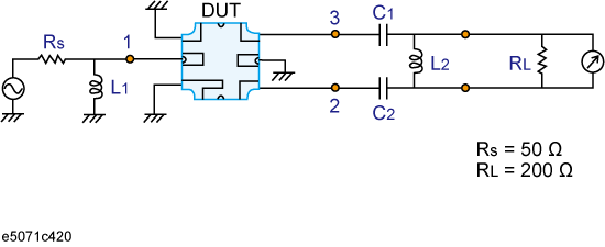
The following figure shows an example of a measurement circuit used to evaluate a balanced SAW filter. DUT port 1 is an unbalanced port connected to source impedance Rs and input matching circuit L1. DUT port 2 is a balanced port connected to an output matching circuit (C1, C2, and L2) and load resistance RL.
Measurement circuit of balance SAW filter

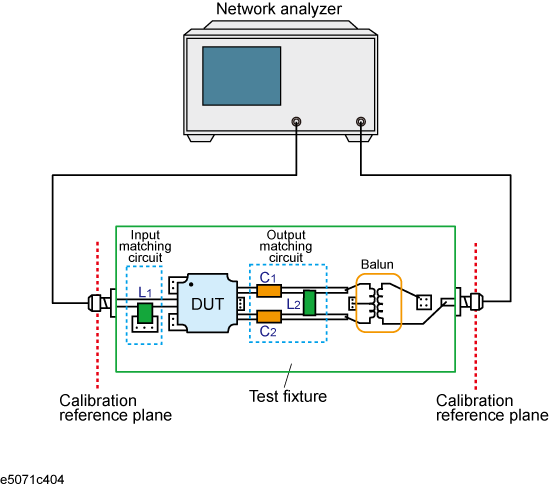
Generally, a test fixture as shown in the following figure is fabricated for evaluating the characteristics of a DUT in a measurement circuit by using a network analyzer.
In typical use, a network analyzer performs measurements at a 50 ohm port reference impedance and in a single-ended (unbalanced) state. Therefore, DUT port 1 can be connected directly to the test port of the network analyzer.
On the other hand, DUT port 2 is a balanced port that cannot be connected directly to the test port of the network analyzer. Usually, a balun (BALance-UNbalance transformer) is used to convert the DUT's balanced port to an unbalanced port and to connect the converted port to the test port of the network analyzer. Matching circuits are mounted in the test fixture as shown in the following figure.
DUT evaluation using an actual test fixture

Evaluating a balanced device with an actual test fixture involves the following problems:
Calibration cannot be performed at the DUT's terminals. (A DUT's terminals are in the test fixture and calibration standards cannot be connected to them. In addition, it is very difficult to obtain calibration standards that can be used to calibrate a balanced port.) As a result, calibration is performed at appropriate connectors connected to the test fixture, and the network between the calibration reference plane and the DUT's terminals induces measurement errors.
Different test fixtures must be fabricated for evaluating different types of DUTs because they require different characteristic impedances and matching circuits.
An actual balun does not have ideal characteristics, so measurement error cannot be avoided. Furthermore, a common mode signal evaluation cannot be performed when an actual balun is used.
The E5071C's fixture simulator function simulates a test fixture by using internal software instead of using an actual test fixture for evaluating DUTs.
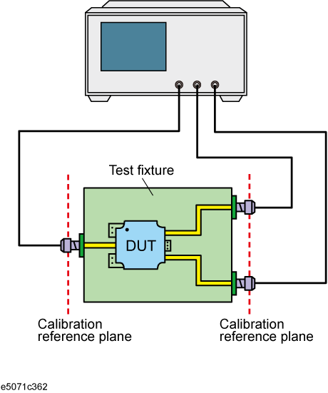
The following figure shows an example connection for evaluating a DUT with the E5071C's fixture simulator function. The unbalanced port of the DUT should be directly connected to a test port of the E5071C, and the balanced port of the DUT should be connected to two other test ports of the E5071C. The actual measurement by the E5071C is performed at single-ended ports with a 50 ohm port reference impedance.
DUT connection when fixture simulator is used

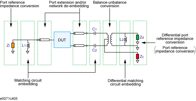
The following figure shows the measurement circuit simulated by the fixture simulator based on actual measurement with the test fixture shown in figure above.
Measurement circuit simulated by fixture simulator

First, the effect of an undesired network can be eliminated by port extension and/or network de-embedding. In the above figure (DUT connection when fixture simulator is used), since calibration standards cannot be connected to the DUT terminals to perform calibration, calibration should be performed at the connectors to the test fixture. Using port extension and/or network de-embedding enables you to remove an undesired network by using data processing and moving the calibration reference plane to the DUT's side equivalently. This function is performed for a single-ended port even if balance-unbalance conversion is applied to the port.
Port reference impedance conversion converts measured S-parameters to those at arbitrary port reference impedance. In the above figure (Measurement circuit simulated by fixture simulator), since the single-ended port of the DUT is connected to the E5071C's test port (50 ohm , single-ended), port reference impedance conversion is not required. This function is performed for a single-ended port even if balance-unbalance conversion is applied to the port.
Matching circuit embedding converts measured S-parameters to those when a matching circuit is added to the DUT's terminal. This function is performed for a single-ended port even if balance-unbalance conversion is applied to the port.
Balance-unbalance conversion converts S-parameters measured at an unbalanced state to mixed-mode S-parameters measured at a balanced state. The balanced port signal can be evaluated by using differential mode and common mode signals.
Differential matching circuit embedding converts measured S-parameters to those when a matching circuit is added to the DUT's differential mode port.(L2 in there figure Measurement circuit simulated by fixture simulator)
Differential port reference impedance conversion converts a differential port reference impedance to an arbitrary impedance. Port reference impedance Z [ohm] at the two single-ended ports before balance conversion is automatically converted to 2Z [ohm] for differential mode port and Z/2 [ohm] for common mode port after balance conversion. Accordingly, if port reference impedance conversion is not performed for the two single-ended ports before balance conversion, differential mode port reference impedance Zd becomes 50 ohm * 2 = 100 ohm , and common mode port reference impedance Zc becomes 50 ohm / 2 = 25 ohm . Since the differential port is terminated with 200 ohm in the figure,Measurement circuit of balance SAW filter, differential port reference impedance Zd should be set to 200 ohm.
Balanced device evaluation using the fixture simulator offers the following advantages:
Calibration reference plane can be easily moved to the DUT's terminal after calibration is performed at the connectors where calibration standards can be connected. Undesired network can be removed to eliminate measurement errors (port extension, network de-embedding).
Characteristics of a DUT, including desired matching circuits, can be obtained easily (matching circuit embedding, differential matching circuit embedding). Port reference impedance can be set freely (port reference impedance conversion, differential port reference impedance conversion).
Differential mode and common mode signal evaluation (mixed-mode S-parameter evaluation) can be performed easily (balance-unbalance conversion).