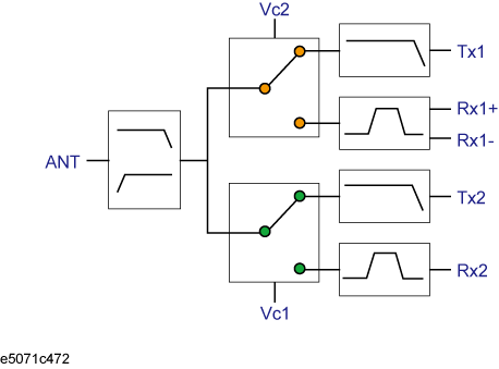
This example shows how to measure the transmission characteristics of a 6-port front end module, as shown in the following figure, by using the E5071C and the E5091A.

In this example, a DUT is evaluated according to the procedure shown in table below.
|
Procedure |
Description |
|
Determine the measurement conditions such as the sweep conditions and measurement ports. |
|
|
Set the allocation of the channel windows on the screen. |
|
|
Determine the test port assignment for each channel. |
|
|
Set the E5091A's control line. |
|
|
Set the sweep range and the number of points. |
|
|
Set the balance port and unbalance port assignment. |
|
|
Set the measurement parameter. |
|
|
Perform calibration using 4-port ECal. |
|
|
Connect the DUT. |
|
|
Execute the measurement and perform auto scale. |
In this example, perform measurement under the measurement conditions in table below.
|
Ch. |
Start frequency |
Stop frequency |
NOP |
Test port assignment |
Control line |
Meas. parameter |
Calibration |
|
|
Type |
Port |
|||||||
|
1 |
400 MHz |
1.4 GHz |
201 |
Port 1 - Port A |
Line 1: Low |
S12 |
Full 2-Port |
1,2 |
|
2 |
880 MHz |
1 GHz |
101 |
Line 1: Low |
Sds21 |
Full 3-Port |
1,3,4 |
|
|
3 |
1.34 GHz |
2.34 GHz |
201 |
Port 1 - Port A |
Line 1: High |
S12 |
Full 2-Port |
1,2 |
|
4 |
1.665 GHz |
2.015 GHz |
101 |
Line 1: Low |
S31 |
Full 2-Port |
1,3 |
|
Set the screen to split into 2 rows and 2 columns to assign channel windows after preset.
|
Setting Description |
Key Operation |
|
Execute preset |
Preset > OK |
|
Allocate channel windows |
Display > Allocate Channels > |
Display the E5091A setup menu and select the 9-port model for ID1.
|
Setting Description |
Key Operation |
|
Display the E5091A setup menu |
System > Multiport Test Set Setup |
|
Select the 9-port model for ID1 |
Test Set 1 > Select Test Set > E5091_9 |
Display the E5091A properties.
|
Setting Description |
Key Operation |
|
Display the E5091A properties |
Property |
Select the test ports assigned to ports 1 to 4 for channel 1.
|
Setting Description |
Key Operation |
|
Assign test port A to port 1. |
Port1 > A |
|
Assign test port T1 to port 2. |
Port2 > T1 |
|
Assign test port R1+ to port 3. |
Port3 > R1+ |
|
Assign test port R1- to port 4. |
Port4 > R1- |
Assign test ports for channels 2, 3, and 4. Press the Channel Next key to switch the active channel and then make the same setting of channel 1.
Enable the control of the E5091A.
|
Setting Description |
Key Operation |
|
Enable the control of the E5091A. |
Control (set it to ON) |
Set the bits of the control line for channel 1.
|
Setting Description |
Key Operation |
|
Set channel 1 to the active channel. |
Channel Next |
|
Line 1: Low |
Control Lines (check only) |
|
Line 2: High |
Control Lines > Line 1 (set it to High) |
Set the control line for channels 2, 3, and 4 according to the same procedure of channel 1.
Set the sweep conditions for channel 1.
|
Setting Description |
Key Operation |
|
Set channel 1 to the active channel. |
Channel Next |
|
Start frequency: 400 MHz |
Start > 4 > 0 > 0 > M/u |
|
Stop frequency: 1.4 GHz |
Stop > 1 > . > 4 > G/n |
|
Number of points: 201 |
Sweep Setup > Point > 2 > 0 > 1 > x1 |
Set sweep conditions for channels 2, 3, and 4 according to the same setting of channel 1.
For channel 2, set the balance conversion topology in order to perform measurement that includes the balanced port.
|
Setting Description |
Key Operation |
|
Set channel 2 to the active channel. |
Channel Next (press it until channel 2 is activated) |
|
Set DUT port 1 to unbalance and DUT port 2 to balance. |
Analysis > Fixture Simulator > Topology > Device > SE-Bal |
|
Set the destination to which DUT port 1 (unbalance) is connected to test port 1 of the analyzer. |
Port 1 (se) > 1 |
|
Set the destination to which DUT port 2 (balance) is connected to test ports 3 and 4 of the analyzer. |
Port 2 (bal) > 3-4 |
|
Unbalance-balance conversion for trace 1: ON |
BalUn (set it to ON) |
|
Fixture simulator: ON |
Fixture Simulator (set it to ON) |
Select the measurement parameter for trace 1 of channel 1.
|
Setting Description |
Key Operation |
|
Set channel 1 to the active channel. |
Channel Next (press it until channel 1 is activated) |
|
Measurement parameter for trace 1: S12 |
Meas > S12 |
The subscript of the measurement parameter means the test port of the E5071C. Check the test port assignment and select the measurement parameter.
Set measurement parameter for channels 2, 3, and 4 according to the same setting of channel 1.
Display the Ecal menu.
|
Setting Description |
Key Operation |
|
Display the ECal menu. |
Cal > ECal |
Set channel 1 to the active channel.
|
Setting Description |
Key Operation |
|
Switch the active channel. |
Channel Next |
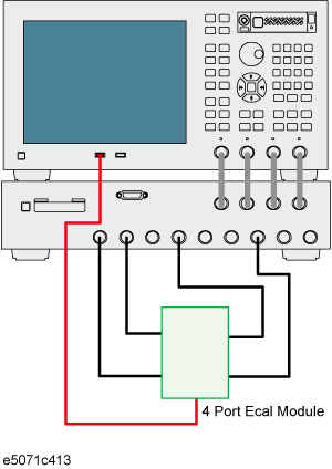
Check the test ports assigned to ports 1 to 4 in the E5091A properties and connect the 4-port ECal module to those port.

Execute the calibration.
|
Setting Description |
Key Operation |
|
Select full 2-port calibration. |
2-Port ECal |
|
Select the port and execute the calibration. |
1-2 |
Perform calibration for channels 2, 3, and 4 according to the same procedure as in Step 2 to Step 4.
Because the test port assignment setting for channels 1 and 2 and that for channels 3 and 4 are the same, you need not change the ECal connection.
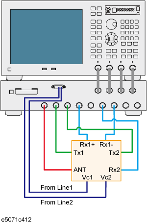
Connect the DUT as shown below.

Display the trigger menu.
|
Description |
Key Operation |
|
Display the trigger menu. |
Trigger |
Set the trigger source to "manual."
|
Setting Description |
Key Operation |
|
Set the trigger source to "manual." |
Trigger Source > Manual |
Set the trigger mode for channel 1 to "continuous."
|
Setting Description |
Key Operation |
|
Set channel 1 to the active channel. |
Channel Next |
|
Set the trigger mode to "continuous." |
Continuous |
Set the trigger mode for channels 2, 3, and 4 to "continuous" according to the same procedure as in Step 3.
Execute the measurement.
|
Setting Description |
Key Operation |
|
Generate a trigger event. |
Trigger |
Repeat the following procedure to execute auto scale for all of the channels.
|
Setting Description |
Key Operation |
|
Set the active channel. |
Channel Next |
|
Execute auto scale. |
Scale > Auto Scale |