This section introduces an example of actually evaluating the unbalanced and balanced SAW bandpass filter with a center frequency of 942.5 MHz. The following figure shows the measurement circuit in the condition for evaluating a DUT.
Here, the DUT is evaluated by following the steps.
|
Step |
Description |
|
The DUT is connected. |
|
|
The measurement conditions are defined. |
|
|
The full 3-port calibration is executed. |
|
|
The balance conversion topology is specified. |
|
|
The mixed-mode S-parameters are selected. |
|
|
6. Extending the Calibration Plane (removing the cause of error) |
The calibration reference plane is extended. |
|
The port reference impedances are specified. |
|
|
A matching circuit is added. |
Connect the DUT to the E5071C by using the instrument's three test ports.

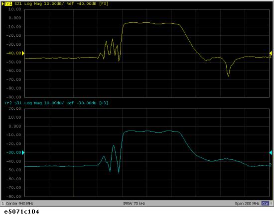
Follow the procedure below to set the measurement conditions. The measurement parameters for balanced measurements should be set after unbalanced-balanced conversion. Here, set the measurement parameters for observing the characteristics achieved during unbalanced measurements.
|
Setting Description |
Key Operation |
|
Preset for setting |
Preset > OK |
|
Center frequency: 940 MHz |
Center > 9 > 4 > 0 > M/u |
|
Frequency span: 200 MHz |
Span > 2 > 0 > 0 > M/u |
|
Number of traces: 2 |
Display > Num of Traces > 2 |
|
Trace-1 measurement parameter: S21 |
Meas > S21 |
|
Trace-2 measurement parameter: S31 |
Trace Next > Meas > S31 |
|
Allocate a trace to upper and lower displays |
Display > Allocate Traces > |
|
Auto-scale all traces |
Scale > Auto Scale All |
Perform a full three-port calibration for the three ports to be used.
Set the type and conditions of calibration.
|
Setting Description |
Key Operation |
|
Calibration kit to use: 85033D |
Cal > Cal Kit > 85033D |
|
Type of calibration: Full three port calibration |
Calibrate > 3-Port Cal |
|
Test ports to calibrate: 1, 2, 3 |
Select Ports > 1-2-3 (check only) |
Perform a reflection calibration.
|
Setting Description |
Key Operation |
|
Select reflection calibration |
Reflection |
|
Perform Port 1 calibration |
(With the OPEN connected) Port 1 OPEN |
|
|
(With the SHORT connected) Port 1 SHORT |
|
|
(With the LOAD connected) Port 1 LOAD |
|
Perform Port 2 calibration |
(With the OPEN connected) Port 2 OPEN |
|
|
(With the SHORT connected) Port 2 SHORT |
|
|
(With the LOAD connected) Port 2 LOAD |
|
Perform Port 3 calibration |
(With the OPEN connected) Port 3 OPEN |
|
|
(With the SHORT connected) Port 3 SHORT |
|
|
(With the LOAD connected) Port 3 LOAD |
Perform a transmission calibration.
|
Setting Description |
Key Operation |
|
Select transmission calibration |
Return > Reflection |
|
Perform a Port 1-to-Port 2 calibration |
(With thru connection) Port 1-2 Thru |
|
Perform a Port 1-to-Port 3 calibration |
(With thru connection) Port 1-3 Thru |
|
Perform a Port 2-to-Port 3 calibration |
(With thru connection) Port 2-3 Thru |
Finish the calibration.
|
Setting Description |
Key Operation |
|
Complete the calibration and then calculate and store calibration coefficients. |
Return > Done (This causes Correction to turn ON.) |
|
Calibration property display: ON |
Return > Return > Property (Turns it ON.) |
Follow the procedure below to set the balanced conversion topology.
|
Setting Description |
Key Operation |
|
Set port 1 on the DUT to unbalanced and port 2 on the DUT to balanced. |
Analysis > Fixture Simulator > Topology > Device > SE-Bal (check only) |
|
Set the connecting destination of port 1 on the DUT (unbalanced) to test port 1 of the analyzer. |
Port 1 (se) > 1 (check only) |
|
Set the connecting destination of port 2 on the DUT (balanced) to test ports 2 and 3 of the analyzer. |
Port 2 (bal) > 2-3 (check only) |
Display four traces.
|
Setting Description |
Key Operation |
|
Number of traces: 4 |
Display > Number of Traces > 4 |
|
Trace allocation: 4-part split |
Allocate Traces > |
Set the measurement parameter (mixed mode S-parameter) and data format for trace 1.
|
Setting Description |
Key Operation |
|
Fixture simulator: ON |
Analysis > Fixture Simulator > Fixture Simulator (turns it ON) |
|
Unbalanced-balanced conversion of trace 1: ON |
BalUn (turns it ON) |
|
Measurement parameter: Sds21 |
Meas > Sds21 |
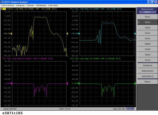
Set the measurement parameter (mixed mode S-parameter) and data format for trace 2.
|
Setting Description |
Key Operation |
|
Unbalanced-balanced conversion of trace 2: ON |
Trace next > Analysis > Fixture Simulator > BalUn (turns it ON) |
|
Measurement parameter: Scs21 |
Meas > Scs21 |
Set the measurement parameter (mixed mode S-parameter) and data format for trace 3.
|
Setting Description |
Key Operation |
|
Unbalanced-balanced conversion of trace 3: ON |
Trace next > Analysis > Fixture Simulator > BalUn (turns it ON) |
|
Measurement parameter: Sss11 |
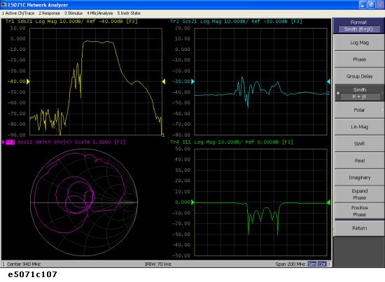
Meas > Sss11 |
|
Data format: Smith chart (marker display: R+jX) |
Format > Smith > R + jX |
Set the measurement parameter (mixed mode S-parameter) and data format for trace 4.
|
Setting Description |
Key Operation |
|
Unbalanced-balanced conversion of trace 4: ON |
Trace next > Analysis > Fixture Simulator > BalUn (turns it ON) |
|
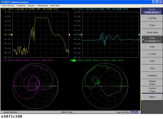
Measurement parameter: Sdd22 |
Meas > Sdd22 |
|
Data format: Smith chart (marker display: R+jX) |
Format > Smith > R + jX |
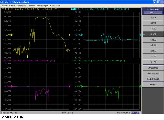
The following figure shows the setting results for each parameter.
In this section you will use the port extension function to remove an electrical delay caused by cables or fixtures located between the calibration reference plane and the DUT to be evaluated. If you can provide a two-port Touchstone data file representing the characteristics of the network to be removed, the network removal function allows you to remove the network and extend the calibration reference plane.
Follow the procedure below to set port extension for each test port.
|
Setting Description |
Key Operation |
|
Port extension of test port 1: 260 ps |
Cal > Port Extensions > Extension Port 1 > . > 2 > 6 > G/n |
|
Port extension of test port 2: 260 ps |
Extension Port 2 > . > 2 > 6 > G/n |
|
Port extension of test port 3: 260 ps |
Extension Port 3 > . > 2 > 6 > G/n |
|
Port extension: ON |
Extensions (turns it ON) |
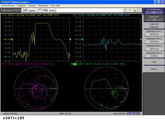
The following figure shows the results of extending the calibration reference plane.
With the reference impedances of two test ports in unbalanced measurements set to Z0, conversion of those ports into balanced ports permits the impedance of the balanced ports' common mode to be automatically set to Z0/2 and the impedance of their differential mode to be automatically set to 2Z0.
Set the port reference impedance of port 1 on the DUT (unbalanced) to 50 ohm.
|
Setting Description |
Key Operation |
|
Reference impedance of test port 1: 50 ohm |
Analysis > Fixture Simulator > Port Z conversion > Port 1 Z0 Real > 5 > 0 > x1 |
In order to set the impedance of the differential mode of port 2 on the DUT (balanced) to 200 ohm , set the impedances of two unbalanced ports before conversion each to 100 ohm.
|
Setting Description |
Key Operation |
|
Reference impedance of test port 2: 100 ohm |
Port 2 Z0 Real > 1 > 0 > 0 > x1 |
|
Reference impedance of test port 3: 100 ohm |
Port 3 Z0 Real > 1 > 0 > 0 > x1 |
Always set the reference impedances of the two test ports before balanced conversion to the same value.
Turn on the port reference impedance conversion function.
|
Setting Description |
Key Operation |
|
Port reference impedance conversion: ON |
Port Z Conversion (turns it ON) |
The reference impedance of the command mode of port 2 on the DUT is set to 50 W . The impedance of the differential mode of that port may be set and modified independently of setting the two-port reference impedances before balanced conversion. For more information, see Converting Reference Impedance of Balanced Port.
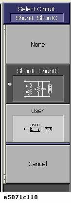
Here, add an inductance of 47 nH in parallel to port 2 on the DUT (balanced). It is also possible to add a matching circuit to the port before unbalanced-balanced conversion. For more information, see Determining the Characteristics that Result from Adding a Matching Circuit to a Differential Port.
The balance matching circuit (Differential matching circuit embedding) is not applied to single-ended S-parameter results. For example, the balance matching circuit is not applied to the imbalance parameter as it is derived from single-ended S-parameters.
|
Setting Description |
Key Operation |
|
Selecting a matching circuit: |
Return (or Analysis > Fixture Simulator) > Diff. Matching > Select Circuit > Shunt L-Shunt C
|
|
Inductance: 47 nH |
L > 4 > 7 > G/n |
|
C=0, G=0, R=0 |
(checks that C, G, and R have been set to 0.) |
|
Differential matching circuit function: ON |
Diff. Matching (turns it ON) |