Other topics about Eye Diagram and Mask Test
The mask test allows you to verify that a displayed waveform complies with industry-standards definitions for electrical waveforms. To comply with the industry standard, the input waveform must remain outside the shaded mask regions. The mask testing is available in Scale/Mask under the Eye/Mask tab. The E5071C-TDR uses the same format as Infiniium DCA (86100C), therefore, you can use the MASK file (.msk) stored by DCA (86100C).
The some masks with industry-standards definitions are available in the E5071C directories.
|
Items |
Description |
|
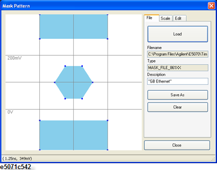
File Name |
Shows the file name and location which is currently selected. The pre-defined files and templates files are available under C:\Program Files\Keysight\E5070\TimeDomain\Masks. |
|
Type |
Shows the Mask File Identifier. In case of Infiniium DCA, this identifier should be "MASK_FILE_861XX". However, the E5071C does not care of this. Even if this is other than "MASK_FILE_861XX", the E5071C accepts it. |
|
Description |
Shows the description of MASK file. You can change this in the Mask Pattern Dialog box. |
Select the Eye/Mask tab.
Click Mask Pattern under Scale/Mask, then the Mask Pattern Dialog box is displayed.
Select the File tab.
Click Load , then the Load Mask Pattern Dialog box is displayed.
Select your desired mask file, then click Open.
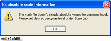
When the following message prompts, define the values of the Logic 1 Lv and Logic 0 Lv in the scale tab and save the file.
Click Close to exit the Mask Pattern Dialog box.
The pre-defined files are read-only file. As you cannot overwrite on them, save the file by clicking Save As.
|
Parameters |
Description |
|
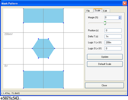
Margin (%) |
Set the size of the mask margin. Mask margins are used to determine the margin of compliance for a standard or scaled mask |
|
Position (s) |
Move X-axis location of mask |
|
Delta T (s) |
Change X-axis width of mask |
|
Logic 1 Lv (V) |
Change voltage of logical 1. |
|
Logic 0 Lv (V) |
Change voltage of logical 0 |
Select the Scale tab.
Change the margin number using slider, or typing number.
Click the box at your desired parameter of position, delta T and logic 0/1 level.
Type the number you want to set.
Click Update to apply the entered number.
Click Close > Yes to save the modified scale.
Click Default Scale to set the parameter at default.
|
Parameter |
Description |
|
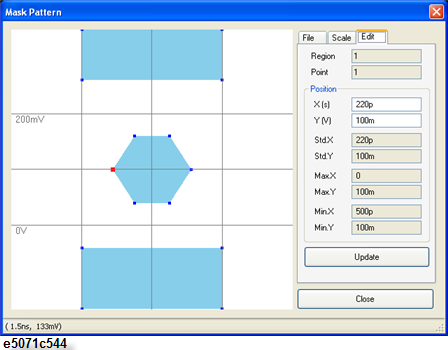
Region |
The currently selected region number. The region number defines a mask violation area (or polygon). |
|
Point |
The currently selected point number. The point number defines a point in the region. |
|
X (s) and Y (V) |
The X and positions for the selected point. You can enter the number to change the selected position location. |
|
Std.X and Std.Y |
The X and Y positions when Margin in Scale Tab is selected at 0%. This shows the positions of STD in the .msk file. |
|
Max.X and Max.Y |
The X and Y positions when Margin in Scale Tab is selected at 100%. This shows the positions of MARGIN_MAX in the .msk file. |
|
Min.X and Min.Y |
The X and Y positions when Margin in Scale Tab is selected at -100%. This shows the positions of MARGIN_MIN in the .msk file. |
Select the Edit tab.
Move the position of points by either way.
Using Mouse
Click the desired point on the figure of mask, then the point is selected (the point color becomes red).
Move the point with drag and drop on the mouse to your desired position.
Entering Position
Click desired point on the figure of mask, then the point is selected.
Click entry box of X(s) under position, then type number for X axis.
Click entry box of Y(V) under position, then type number for Y axis.
Click Update to apply the entered number on the selected point.
Click Close > Yes to save the modified pattern.
Select the Mask Test check box under Scale/Mask.
Click Draw Eye to redraw Eye pattern and Mask.
The mask and pass/fail result is displayed on the screen.