Other topics about Measurement Wizard Assistant
The front-end application of the MWA creates a setup file named "spec sheet" (.mwa) which is used in the back-end application on the VNA. The procedure of creating a spec sheet is described below:
Start Excel and select File > Open.
In the window that opens, select mwa_xxxx.xls and click Open.
When you are asked whether to enable macros, select the option to enable them.
Note: When opening the front-end application of MWA in Microsoft Office Excel 2010/2013, the macros of the front-end are disabled by default as indicated by “Security Warning” tab. In order to use the front-end application, its macros must be enabled. To enable the macros, click “option” button on “Security Warning” tab and select either “Enable this content” or “Trust all documents from this publisher” on the pop-up “Security Alert – Macros & ActiveX” window.
The procedure for selecting the configuration of measurement in the "Multiport Test Set" sheet is described below:
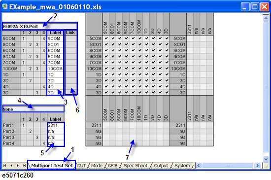
Select the "Multiport Test Set" tab ([1] in Multiport Test Set Sheet)
Double-click the selection cell for test set 1 ([2] in Multiport Test Set Sheet) and select the first multiport test set in the drop-down list. The following configurations are available with the MWA:
|
No. |
Test Sets |
Description |
|
0 |
None |
Uses the 4-port VNA only. |
|
1 |
E5091A 9-Port |
E5080A does not support E5091A. |
|
2 |
E5091A 13-Port |
E5080A does not support E5091A. |
|
3 |
E5091A 16-Port |
E5080A does not support E5091A. |
|
4 |
Uses the 13-port configuration of the E5092A option 020 (E5092A-020). |
|
|
5 |
Uses the 16-port configuration of the E5092A option 020 (E5092A-020). |
|
|
6 |
Uses the 22-port configuration of the E5092A option 020 (E5092A-020). |
|
|
7 |
Uses the 10-port full crossbar configuration of the E5092A option 020 (E5092A-020). |
|
|
8 |
Z5623AK64 |
This is a test set designed for the PNA-L (N5230A option 245). It cannot be used with the VNA. |
|
9 |
Z5623AK66 |
This is a test set designed for the PNA-L (N5230A option 245). It cannot be used with the VNA. |
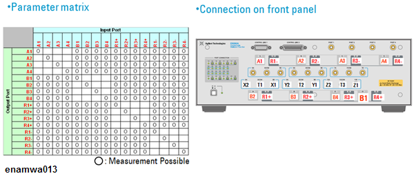
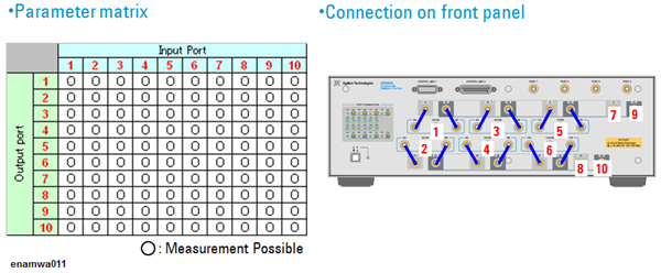
E5092A 13-Port Switching Configuration
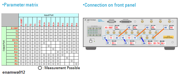
E5092A 13-Port Configuration Parameter Matrix & Front Panel Connection
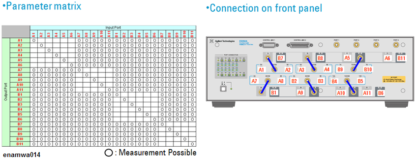
E5092A 16-Port Configuration
E5092A 16-Port Configuration Parameter Matrix & Front Panel Connection
E5092A 22-Port Configuration
E5092A 22-Port Configuration Parameter Matrix & Front Panel Connection
E5092A 10-Port Full Crossbar Configuration
E5092A 10-Port Full Crossbar Configuration Parameter Matrix & Front Panel Connection
Type the label names of ports in a cell of the Label column for test set 1 ((3) in Multiport Test Set Sheet). The label names typed here will be used in the following procedure of the front-end and the back-end application.
Note: The functionality to Copy & Paste is not available in the front-end application of the MWA. Make sure to type characters and values or select the option from the drop-down list.
Double-click the selection cell for test set 2 ((4) in Multiport Test Set Sheet) and select another multiport test set in the drop-down list. Following configurations (following table) are available for the second test set:
|
No. |
Test Sets |
Description |
|
0 |
None |
Does not use a second test set. |
|
1 |
E5091A 9-Port |
E5080A does not support E5091A. |
|
2 |
E5091A 13-Port |
E5080A does not support E5091A. |
|
3 |
E5091A 16-Port |
E5080A does not support E5091A. |
|
4 |
Uses the 13-port configuration of the E5092A (E5092A-020). |
|
|
5 |
Uses the 16-port configuration of the E5092A (E5092A-020). |
|
|
6 |
Uses the 22-port configuration of the E5092A (E5092A-020). |
|
|
7 |
Uses the 10-port full crossbar configuration of the E5092A (E5092A-020). |
Note: Step 4 through Step 6 is required when two multiport test sets are used for measurement. When only one test set is used, select None and proceed to Step 7.
Type the label names of the ports in cells in the Label column for the test set 2 ((5) in Multiport Test Set Sheet).
Set the number 1 to 4 in the cells in the Link column ((6) in Multiport Test Set Sheet), which correspond to the ports 1-4 of the second test set.
When the selection of measurement configuration is completed, the connectivity matrix in the right ([7] in Multiport Test Set Sheet) is automatically updated. Those checked in the table are the paths that can be measured.
The procedure for defining the characteristics of the DUT and the connection with the ports on the VNA or the multiport test set are explained below.
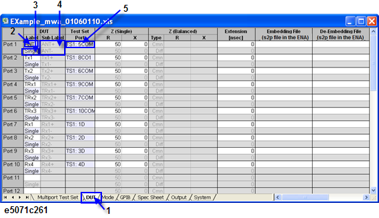
Select the "DUT" tab ([1] in DUT Sheet (1/3)).
Type a label name in a cell in the DUT Label column ((2) in DUT Sheet (1/3)) that defines the connection between the DUT and a test set. Typing the label name in the cell enables the corresponding port of the VNA or the multiport test set.
Double-click the port type selection cell ((3) in DUT Sheet (1/3)) below the DUT Label and select a port type from the drop-down list or directly input the port type number (1-3). The following types are available:
|
No. |
Port Types |
Description |
|
1 |
Single |
Sets the port type to single-ended port. |
|
2 |
Common |
Sets the port type to common-mode port. |
|
3 |
Differential |
Sets the port type to differential-mode port. |
If you select Common or Differential as the port type, type into a cell in the Sub Label column ((4) in DUT Sheet (1/3)) a label name that will be used when the ports are connected to the single-ended ports on the VNA or the test set.
Double-click the port selection cell ((5) in DUT Sheet (1/3)) and select a port of the test set from the drop-down list. Selection can be made from the ports that have been pre-defined in the Multiport Test Set sheet.
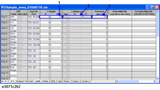
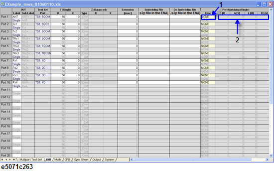
When you set the port type to Single, enter port impedance in cells in the R (for the real part) and X (for the imaginary part) columns ([1] in DUT Sheet (2/3)) under Z (Single). When you set the port type to Common or Differential, enter impedance in cells of the R and X columns ((2) in DUT Sheet (2/3)) under Z (Balanced).
Enter into a cell in the Extension column ((3) in DUT Sheet (2/3)) an extension time that is applied when the port is extended. If you set the port type to something other than Single, enter an extension time for each of the two ports.
Note: Embedding and de-embedding functions are available in front end application. Embedding and Port Matching cannot be used at the same time because of the VNA firmware specification.
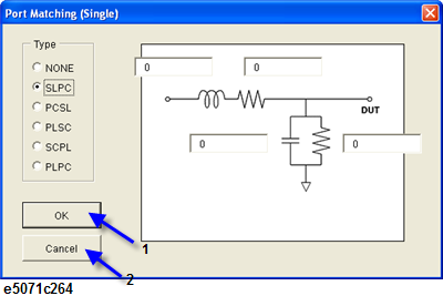
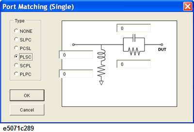
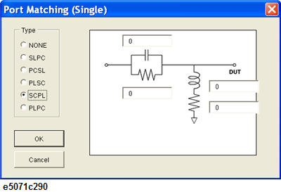
Double-click a cell in the Type column under Port Matching (Single) ((1) in DUT Sheet (3/3)) to display a dialog box for setting the port matching circuit (Dialog box for setting the port matching circuit). Select a type, enter values for C, G, L and R and click OK ((1) in Dialog box for setting the port matching circuit). To return to the DUT sheet without setting the type and the values, click Cancel ((2) in Dialog box for setting the port matching circuit).
The units of C, G, L and R are F (farad), S (siemens), H (henry) and ohm, respectively. An exponent is acceptable as an input format.
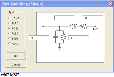
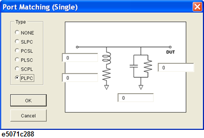
The types of the port matching circuits are as follows:
|
Types of Port Matching Circuits |
Description |
|
None |
No matching circuit is selected. |
|
Selects the circuit that consists of series L and shunt C. |
|
|
Selects the circuit that consists of shunt C and series L. |
|
|
Selects the circuit that consists of shunt L and series C. |
|
|
Selects the circuit that consists of series C and shunt L. |
|
|
Selects the circuit that consists of shunt L and shunt C. |
Note: Values can be entered directly in cells in the C, G, L and R columns ((2) in DUT Sheet (3/3)) instead of using the dialog box.
Repeat Step 2 through Step 8 as many times as needed to set all the required parameters.
Dialog box for setting the port matching circuit
The E5092A multiport test set has the capability of DC source that can supply the bits of DC control voltage to a DUT. By selecting L (Low) or H (High) voltage for each control bit, the operation mode of the DUT can be determined. The procedure for setting operation mode in the "Mode" sheet is explained below:
Select the "Mode" tab ((1) in Mode Sheet).
Turn ON each cell for the status of operation mode of the DUT ((2) in Mode Sheet).
Enter a preferred label name in a cell in the Mode Label column ((3) in Mode Sheet). The label name entered here will be used as a tag name of a generated spec sheet. It will also be used by the back-end application as a label.
Double-click cells for control voltage (Vc1 through Vc8) under Control Line Voltage [TS1] of the first test set ((4) in Mode Sheet) and set L (Low) or H (High) voltage for each control line. It is also possible to directly input the number 0 or 1 (0 for Low, 1for High).
When you use two test sets, you can set control voltage outputs from the second test set. Set cells for Vc1 through Vc8 under Line Voltage [TS2] of the second test set ((5) in Mode Sheet) the same way as in Step 4.
Repeat Step 2 through Step 5 as many times as needed to set all desired modes.
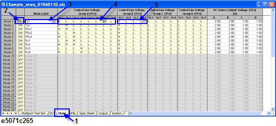
Note: Control Line Voltage Group (A to D) and DC Source Output Voltage options are available only when E5092A test set has been selected in the Multiport test set tab. The DC source output voltage range varies between 1V-5V with a resolution of 0.01V depending upon the specification of E5092A.
Note: The maximum number of modes is 40.
DC Source and Control Line Voltage Diagram
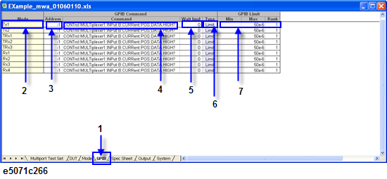
The procedure explained below is for setting GPIB commands to external peripherals in the "GPIB" sheet. A USB/GPIB interface (i.e. Agilent 87357B) to connect the VNA and peripherals with the GPIB interface is necessary for this function.
Select the "GPIB" tab ((1) in GPIB Sheet).
Under GPIB Command, enter into a cell in the Address column ((3) in GPIB Sheet) the GPIB address of the external peripherals to which GPIB commands will be sent.
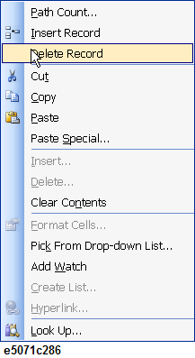
Note: To add a new command row to a mode, double-click the cell in the Mode column((2) in GPIB Sheet). To delete a command row from a mode, place the cursor at the row that you want to delete, right-click to display a list, and select Delete Command.
To add multiple rows at one time, place the cursor at the row of the command to which you want to add the new rows, right-click to display the Command Count dialog and set the number of rows as needed in the particular mode.
Note: GPIB commands can be sent to the VNA itself by entering -1 into a cell in the Address column.
Enter into a cell in the Command column ((4) in GPIB Sheet) a GPIB command to be sent.
Note: Single or double quotation is required for the parameter of string. Example :DISP:WIND1:TITL:DATA 'Sample1'
Enter the wait time into a cell in the Wait [ms] column ((5) in GPIB Sheet) under GPIB Command. This wait time (in msec) should be set to insert the data transaction time between the VNA and a peripheral in the testing system, when a query command is sent to the peripheral during the measurement.
Double-click a cell in the Type column ((6) GPIB Sheet) to display a drop-down list and select the desired command type. The following options are available:
|
No. |
Command Type |
Description |
|
1 |
Limit |
Set this where a query command is sent via GPIB. The returned value is used in the limit test by the back-end application. |
|
2 |
Pre |
Set this where a GPIB command is sent before measurement starts in the back-end application. |
|
3 |
Post |
Set this where a GPIB command is sent after measurement ends in the back-end application. |
Note: The command type can be set only for GPIB commands that have been set in Setting Operation Mode of the DUT. GPIB command types cannot be set in INIT mode.
Note: In INIT mode, a command is executed only once when spec sheets are read by the back-end application. Since this execution of the commands takes place before measurement, set such commands to initialize the state of an external peripheral.
When Limit is selected for the command type, enter the lower limit value, the upper limit value and a rank number in cells in the Min, Max and Rank columns ((7) in GPIB Sheet), respectively. These figures are used in the limit test by the back-end application on a returned value of a query command to the peripherals. For details on the rank, refer to Step 11 in Setting Measurement Parameters in Each Mode.
Note: The lower limit values, the upper limit values, and the ranks can be set in cells under GPIB Limit only if the selected GPIB command type is Limit. This does not apply to Pre or Post GPIB commands. This setting cannot be performed for GPIB commands in the INIT mode either.
Repeat Step 2 through 6 as many times as needed to set GPIB commands in each mode.
The procedure described below is for setting all the measurement parameters of modes that are pre-defined in Setting Opeartion Mode of the DUT.
Select the "Spec Sheet" tab ((1) in Spec Sheet (1/2)).
Double-click the From column under Path ((3) in Spec Sheet (1/2)) and select a DUT port that is connected to the source port of the VNA from the drop-down list. The selection can be made from the ports that have been defined in Defining the DUT and Connecting to a Test Set.
Note: To add a new row to a measurement path, double-click the cell in the Mode column ((2) in Spec Sheet (1/2)). To delete a row of a measurement path, place the cursor at the row you want to delete, right-click to display the list, and select Delete Record.
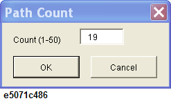
To add multiple new measurement paths, place the cursor at the mode, right-click and select Path Count...In the displayed Path Count dialog, set the number of paths as needed.
As in Step 2, double-click a cell in the To column under Path ((3) of Spec Sheet (1/2)) to display a drop-down list and select a DUT port that is connected to the receiver port of the VNA.
Double-click a cell in the Type column ((4) in Spec Sheet (1/2)) to display a drop-down list and select measurement type for each path. The following types can be selected:
|
No. |
Measurement Type |
Description |
Parameter |
Data Format |
|
1 |
IL |
Performs the Insertion Loss measurement |
Transmission |
LogMag |
|
2 |
Ripple |
Performs the Ripple measurement |
Transmission |
LogMag |
|
3 |
VSWR |
Performs the Voltage Standing Wave Ratio measurement |
Reflection |
VSWR |
|
4 |
RL |
Performs the Return Loss measurement |
Reflection |
LogMag |
|
5 |
ATT |
Performs the Attenuation measurement |
Transmission |
LogMag |
|
6 |
Isolation |
Performs the Isolation measurement |
Transmission |
LogMag |
|
7 |
BalAmp |
Performs the Imbalance measurement with balanced port. (in magnitude) |
Imbalance |
LogMag |
|
8 |
BalPhase |
Performs the Imbalance measurement with balanced port. (in phase) |
Imbalance |
Phase |
|
9 |
Phase |
Performs the Phase measurement. |
Reflection / Transmission |
Phase
|
|
10 |
Group Delay |
Performs the Group Delay measurement. |
Reflection / Transmission |
Group Delay |
|
11 |
Lin Mag |
Performs the measurement in linear magnitude. |
Reflection / Transmission |
LinMag |
|
12 |
Real |
Performs the measurement in real. |
Reflection / Transmission |
Real |
|
13 |
Imag |
Performs the measurement in imaginary. |
Reflection / Transmission |
Imaginary |
Note: The limit test is performed by the back-end application with the limit values in the spec column. (Described in Step 8). The sign change is required for the limit test value in case of the IL, RL, ATT or Isolation measurement type. For example, the maximum -5dB of insertion loss is the allowable specification of the DUT, input 5 (dB) in the maximum (Max) value in the spec column. If you need the isolation at least below -80dB in the measured path, you should input 80 (dB) in the minimum (Min) value in the spec column for the limit test.
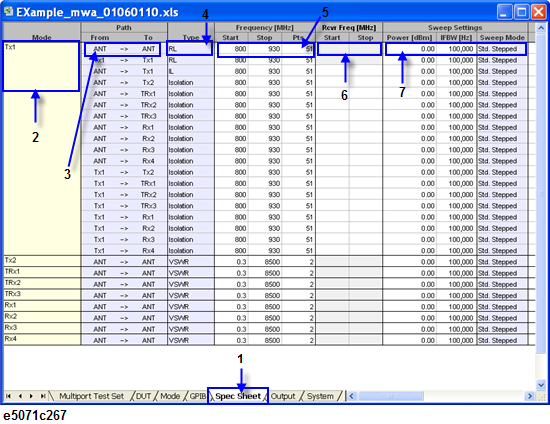
Enter the start frequency, the stop frequency and the number of measurement points in the cells in Start, Stop and Pts columns ((5) in Spec Sheet (1/2)) under Frequency [MHz]. These figures will be the sweep settings that are used to perform measurement by the back-end application of the VNA.
Frequency offset mode is available with the MWA by entering the start and stop frequency at the receiver port on the VNA in cells in the Start and Stop columns ((6) in Spec Sheet (1/2)) under Rcv Freq [MHz].
Set the output level, the IF bandwidth and the sweep mode of a port on the output side using cells in the Power, IFBW [Hz] and Sweep Mode columns under Sweep Setting ((7) in Spec Sheet (1/2)). Double-click the sweep mode cell to display a drop-down list and select a sweep mode of the VNA. The following options are available:
|
No. |
Sweep Modes |
Description |
|
1 |
Std. Stepped |
Sets the sweep mode to the stepped mode. |
|
2 |
Std. Swept |
Sets the sweep mode to the swept mode. |
|
3 |
Fast Stepped |
Sets the sweep mode to the fast stepped mode (This mode is only for the E5070B/E5071B.) |
|
4 |
Fast Swept |
Sets the sweep mode to the fast swept mode (This mode is only for the E5070B/E5071B.) |
Enter the limit values of a measurement parameter in cells in the Min and Max columns ((1) in Spec Sheet (2/2)) under Spec column. The values entered here will be used for the limit test in the back-end application to evaluate measured parameters. If no values are entered in the cells, -999 is assumed for Min (lower limit) and 999 for Max (upper limit).
The measured data can be converted in the back-end application. In such cases enter correction values in cells in the Start and Stop columns under Corr. Multiplier ((2) in Spec Sheet (2/2)) and cells in the Start and Stop columns under Corr. Offset((3) in Spec Sheet (2/2)). The correction is done on the measured data at the start frequency and the stop frequency with the entered multiplier and offset values. The measured data on each point in between the two frequencies is linearly interpolated.
A cell in the Diff (difference) column under Corr. ((4) in Spec Sheet (2/2)) can be checked by double clicking. When a path has a check mark in this cell, the difference between the corrected value in the first path and the other checked paths of the mode can be tested between in the back-end application.
This feature can be used for harmonic measurement (in dBc) by entering the parameters at the carrier frequency in the first path and the parameters at the harmonic frequencies in the next paths.
Note: The first path in each mode cannot be checked because it is automatically assigned as the measurement reference for calculating differences from the other paths.
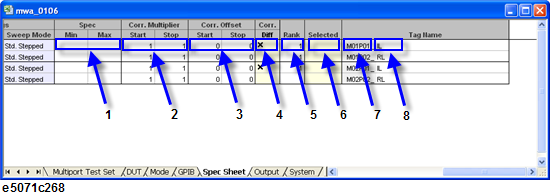
Enter a rank number into a cell in the Rank column ((5) in Spec Sheet (2/2)) Rank can be used to prioritize the test result of measurement paths of the DUT. The rank number can be ranged from 0 to 255 and the lowest number of the rank is outputted to the handler I/O on the VNA by the back-end application after the completion of the limit test. This will indicate the most critical failure of the measurement path of the DUT in the limit test. When the test result gives the pass for all measurement paths, the returned rank number is 0.
A cell in the Selected column ((6) in Spec Sheet (2/2)) can be checked by double-clicking. The measurement of the path with the checked mark in the cell is performed in the back-end application. You can select in the back-end application whether to apply the selective measurement or not.
Enter the tag name of a measurement path in cells into the Tag Name columns ((7) and (8) in Spec Sheet (2/2)). The first part of the tag name ((7) in Spec Sheet (2/2)) is assigned automatically with the corresponding mode and path number, and cannot be modified. The second part of the name ((8) in Spec Sheet (2/2)) can be changed as needed.
Repeat Step 2 through Step 13 as many times as needed to set up measurement path details in each mode.
The procedure explained below is for verifying the contents of the settings and generating a spec sheet for the back-end application in the “Output” sheet.
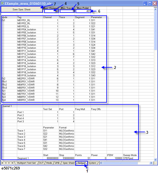
Select the "Output" tab ((1) in Output Sheet).The channel and trace allocation of each measurement path on the VNA is automatically displayed in the sheet
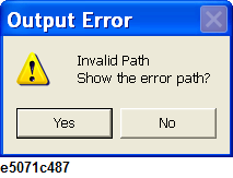
Note: An error message dialog is displayed if there is any invalid input in the previous sheets of the front-end application. Press Yes in the dialog to return to the portion that caused the error.
Enter the maximum channel number of the VNA in the Max Channel cell ((4) in Output Sheet), the maximum number of traces per channel in the Max Trace cell ((5) in Output Sheet), and the maximum number of measurement points in the Max Point cell ((6) in Output Sheet) at the top of the "Output" sheet.
Based on the values entered here, all the measurement paths in all the modes are automatically allocated to appropriate channels.
Information on all the measurement paths in all the modes and corresponding channels, traces, and segments is shown in the Output sheet ((2) in Output Sheet). Check the information and correct the corresponding sheet if there are any errors.
Detailed information on each channel including the test set ID, connected port number of the test set, measurement parameters on each trace is displayed ((3) in Output Sheet). Check the information and correct the corresponding sheet if there are any errors.
If all information shown in the Output sheet is correct, press Save Spec Sheet ((7) in Output Sheet) at the top of the sheet to display the Save dialog box. Select a folder and enter a preferred file name and press Save to generate and save a spec sheet, which will be used by the back-end application.
The procedure explained below is for importing/exporting the parameters in the csv format with the "System" sheet.
Select the "System" tab ((1) in System Sheet).
Press Export ((3) in System Sheet) to display the Export Data dialog box.
Enter a file name and press OK. All the entered parameters in the front-end application are exported to a file in csv format.
To import the parameters from a csv files, press Import ((2) in System Sheet) to display the Import Data dialog.
Select a csv file to read and press OK. The parameters in the csv file can be imported in the front-end application.
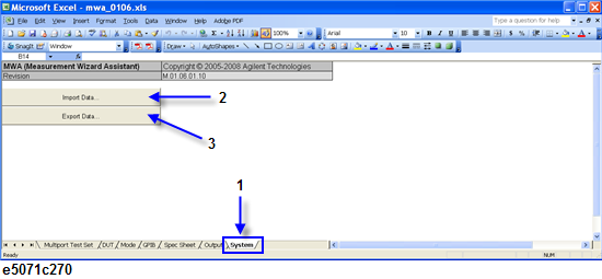
Note: Because the exported file (.csv) is not a spec sheet,(.mwa) generated in the “Output” sheet, it cannot be recalled in the back-end application.