Other topics about Mixer Calibration
The VNA has a vector-mixer calibration function for use in measuring frequency conversion devices.
The vector-mixer calibration allows you to measure the magnitude, phase and group delay of the mixer's conversion loss by using in combination calibration standards (OPEN/SHORT/LOAD) and calibration mixer with an IF filter, as well as the network de-embedding function incorporated in the VNA.
Note: For Fixed RF measurement (RF: Fixed, LO and IF: Swept), it is NOT possible to perform vector-mixer calibration because touchstone file, which defined with fixed frequency, can not be imported to ENA.
Note: For Fixed IF measurement (RF and LO: Swept, IF: Fixed), it is possible to perform vector-mixer calibration and to measure conversion loss and return loss, but NOT possible to measure group delay because IF frequency is fixed.
Note: For Swept IF measurement (RF and IF: Swept, LO: Fixed), it is possible to perform vector-mixer calibration and to measure conversion loss, return loss and group delay.
You can also perform balanced mixer measurements by using two calibrations mixers that each has an IF filter.
Vector-mixer calibration is implemented by eliminating the characteristics of the calibration mixer and IF filter by using the network de-embedding function after full 2-port calibration has been completed. Using the up/down conversion method allows you to specify the same sweep measurement frequency for the input and output ports, thus enabling full 2-port calibration at the end of the target port. Consequently, only the characteristics of the measured mixer (DUT) can be obtained by using the network de-embedding function, after eliminating the characteristics of the calibration mixer with an IF filter from all measurement results.
Note: Since the up/down conversion method is used in vector-mixer calibration, the frequency-offset function is not used. But, option 009 is required to use the VMC macro, SG control, and etc.
The vector-mixer calibration requires the characteristics data for the calibration mixer with IF filter.
A measured mixer (DUT) signifies an unknown target mixer of measurement. However, a measured mixer meeting the requirements for a calibration mixer can be used as a calibration mixer.
The calibration mixer is required for supporting the measurement system of the up/down conversion. You must also evaluate in advance the frequency response characteristics of the calibration mixer. The vector-mixer calibration method obtains the characteristics of the measured mixer alone by using the network de-embedding function to eliminate the characteristics of the calibration mixer from the measurement result. You can use the IF filter to select any required frequency conversion component such as RF+LO, RF-LO, and LO-RF. The calibration mixer and IF filter can be seen as a part of the test system setup, just like the network analyzer and the test cable; they are connected at the same location during the entire calibration or measurement.
Note: The frequency range must be equal to or greater than that of the measured mixer. If you want to test multiple mixers with a single setup, select a wide range of calibration mixers that can cover all frequencies of the target test devices.
In vector-mixer calibration, you must characterize the calibration mixer with the IF filter. As shown in the following figure, connect the target mixer (with IF filter) to the port of the network analyzer on which vector calibration has been performed and then connect an OPEN, SHORT or LOAD standard to the end of the IF filter to start reflection measurement. The signals measured at the test port include the reflection signal from the mixer's RF port, the IF signal (IF+) converted by the mixer and then reflected by the IF filter, and the IF signal (IF-) passing through the IF filer and then reflected by the calibration standard.
The characteristics of the calibration mixer can be described in a 1-port error model, and each error item can be determined from ΓO, ΓS, and ΓL, which are obtained in the reflection measurement of individual standards.
Characteristics evaluation of calibration mixer (with IF filter)
Note: The calibration mixer must be reciprocal. The term "reciprocal" means the magnitude and phase of the conversion loss are equal both in the forward and reverse directions. The forward conversion loss occurs during the measurement of the output signal at the IF port while inputting measurement signals into the RF port. In contrast, the reverse conversion loss occurs during measurement of the output signal at the RF port while inputting measurement signals into the IF port.
Note: For precise calibration, the conversion loss in each direction must be less than 10 dB using a calibration mixer and IF filter in combination. Exceeding 15 dB of the conversion loss in any direction may deteriorate the calibration accuracy significantly.
Set the stimulus conditions for the channel you want to calibrate. You must also set the external signal source in advance.
Note: Full 2-port calibration is recommended for characterizing the calibration mixer with the IF filter, although 1-port calibration is also available. This is because using full 2-port calibration simplifies the evaluation procedures.
In Standard measurement class, clicking Cal > Other Cals > Mixer Characterization....
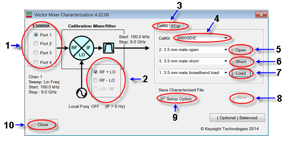
Select the 1-port calibration port (1 in menu).
Select IF frequency from RF+LO, RF-LO and LO-RF (2 in menu), depending on the IF frequency of the calibration mixer.
Note: The number displayed in the Vector Mixer Characterization macro is the frequency set in the VNA and read from it. You must also set the minimum IF frequency at more than 0 kHz.
IF BW must be set to much smaller value than IF frequency.
Select a calibration kit (3 in menu).
Note: The mechanical calibration kit displayed in the Vector Mixer Characterization macro is the frequency registered in the VNA and read from it. If an ECal module is connected to the VNA, ECal will be selected automatically.
Connect the calibration mixer to one of the test ports on which 1-port calibration has been done, as shown in the following figure.
Connection of calibration mixer (with IF filter)
Note: Select any port if full 2-port calibration is set.
Note: We recommend that you characterize the calibration mixer with an IF filter when the power splitter for distributing the LO signal is connected to the measured mixer. In vector-mixer calibration, where the up/down conversion method is used, the power of the LO signal is distributed to the calibration mixer and the measured mixer through the power splitter. During a characteristics evaluation of the calibration mixer, the LO power level used by the drive of the calibration mixer must be equal to the LO power level with the measured mixer connected. This is because the mixer's conversion loss and reflection coefficient are significantly affected by the power level of the LO signal.
Select CalKit (3 in menu).
Select the type number of the calibration kit from CalKit menu (4 in menu).
Click the Open button (5 in menu) to start measurement in OPEN.
Click the Short button (6 in menu) to start measurement in SHORT.
Click the Load button (7 in menu) to start measurement in LOAD.

Select ECal (1 in menu).
Select the port used for the ECal module (2 in menu).
Click the Measure button (3 in menu) to start measurement.
Select the property and click info (4 in menu) to see the measurement.
Press the Save button (8 in menu) to open the Save screen.
Press the Save button to specify a name for the characteristic data of the calibration mixer with IF filter. Then save it to a Touchstone file. If you check the Setup Option (9 in menu), the saved characteristic data will be set for the specified port of the active channel as the characteristic data file of the network de-embedding, and the fixture simulator function will be enabled. If unchecked, only the characteristic data will be saved.
Click the Close button (10 in menu) to exit the macro.
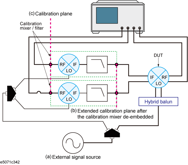
The Vector Mixer Characterization macro provided with the VNA allows you to characterize the calibration mixer (with IF filter) to be used for the balanced mixer measurement. The characterizing procedures of the calibration mixer with IF filter used for balance mixer measurement are basically the same as those used for normal mixer measurement; however, two characteristic data of the calibration mixer with IF filter are required for balanced mixer measurement, as shown in the following figure.
Connect the target calibration mixer (with IF filter) to the port of the network analyzer on which calibration has been performed and then connect the OPEN, SHORT and LOAD standards to the end of the IF filter to start reflection measurement and characterization. For a balanced mixers, the phase difference of the LO signals between the calibration mixers with IF filter will remain as an error, since each calibration mixer with IF filter is characterized independently. Therefore, you must calibrate the phase difference between the two characterized calibration mixers with IF filters.
Characteristics evaluation of calibration mixer (with IF filter) for balance mixer
Note: We recommend that you use the same products of calibration mixers, IF filters and cables between the balanced ports to which each calibration mixer (with IF filter) is connected.
You should keep the following electrical lengths the same between the two ports to which the calibration mixer is connected as much as possible - the electrical length from the external signal source output port (a) to the extended calibration plane (b), and the electrical length from the calibration plane (c) to the extended calibration plane (b). Large electrical length differences between the two ports to which the calibration mixer is connected could raise 180 degrees phase value error between the two IF ports even though the Balanced Mixer Calibration Macro is executed. You can verify it by swapping the IF cable connections with each other.
Measure the characteristic data of each calibration mixer with the IF filter used for balanced mixer measurement, using any two ports.
Set the stimulus conditions for the channel you want to calibrate. You must also set the external signal source in advance.
Note: If you characterize a calibration mixer with an IF filter, we recommend that you perform full 4-port calibration in advance, since it simplifies the evaluation procedures.
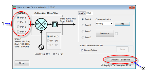
Press Macro > Macro 1 > VMC.
Select Port 1 (1 in menu) to characterize the calibration mixer 1 with IF filter. In this case, the data are saved to a temporary file (MIXER_1.s2p).
Select Port 2 (1 in menu) to characterize calibration mixer 2 with IF filter. Here, the data are also saved to a temporary file (MIXER_2.s2p).
Note: For detailed information on characterizing the calibration mixer, see Characterizing procedure for calibration mixer (with IF filter).
Click (Optional) Balanced Mixer (2 in menu).
As the Vector Mixer Characterization Macro is running, the data files of the pre-measured calibration mixer with IF filter (MIXER_1.s2p, MIXER_2.s2p) are read automatically into the macro (1 in menu).
Note: If failure occurs when reading the data file for the calibration mixer with IF filter, the characterization may have done by using only one port instead of using two ports.

Select the measurement port (2 in menu) and then connect a THRU between the IF ports of the calibration mixers to correct the phase difference of the LO signals for the calibration mixers with IF filters.
Pressing the Execute (3 in menu) button executes a phase error correction and overwrites the results on the original data file.
You cannot run the Execute function when selecting the measurement port if the data file of the calibration mixer with IF filter (*.s2p) has not been set for the network removal function of the fixture simulator.
The phase error correction data reflects the phase difference of the LO signals for the phase information of the calibration mixer's data file, which is registered in any two ports.
Press the Close button (4 in menu) to exit macro.