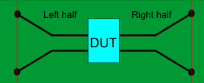
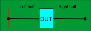
Automatic Fixture Removal (AFR)


Note: This feature requires Option S9x007A or 007.

In this topic:

Overview

Fixtures are often used for DUTs that have non-coaxial interfaces. This feature allows you to mathematically remove, or de-embed, a characterized test fixture from displayed measurement results of the test fixture and DUT.

Before starting the AFR process, Perform a calibration at the connectors of the test fixture (red lines in images below).

The AFR Wizard will guide you through these steps:

  1. Press Cal > Fixtures > Auto Fixture Removal....

  2. Describe your fixturing situation.

  3. Specify How the Thru fixture characterization will occur.

  4. Do characterization.

  5. Remove the effects of the test fixture. Leaves ONLY the displayed results of the DUT.

  6. Touchstone files are saved that characterize the two halves of the test fixture.

Requirements

Single-ended Fixtures

Test fixture

Thru standard


OR

Left and Right halves of Thru standard


Supports both 1-port (not shown) and 2-port single-ended DUT configurations.

When used with a 4-port DUT configuration, the trace coupling is not removed.

Differential (Balanced) Fixtures

Test fixture

Thru standard


OR

Left and Right halves of Thru standard


Supports 4-port DUT configuration ONLY which includes removing the effects of coupling between the differential traces.

How to start the Automatic Fixture Removal Wizard

With a calibrated measurement of the DUT in the test fixture present:

Click Response, then Cal, then Fixtures, then Automatic Fixture Removal

Note: The dialogs below show images for a Single ended DUT, but Differential works exactly the same, only with Differential S4P files.


Automatic Fixture Removal Wizard

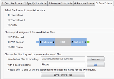
For best results, follow the AFR Wizard tabs from steps 1 through 5 by either clicking Next > or clicking the tabs.

In this section:

  1. Describe Fixture

  2. Specify Standards

  3. Measure Standards

  4. Remove Fixture

  5. Save Fixture


1. Describe Fixture

The choices that you make in the dialog are reflected in the diagram and text (red box in following image).

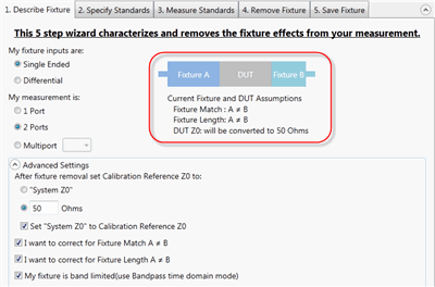
My fixture inputs are:

  • Single Ended - The fixture and DUT have single-ended inputs and outputs.

  • Differential - The fixture and DUT have differential inputs and outputs.

My measurement is:

  • 1-port - such as S11.(single-ended only)

  • 2-port - such as S21 (single-ended) or SDD11 (differential)

  • 4-ports - such as SDD21 (differential only)

  • Multiport - available when using a testset with more than 4 ports.

Advanced Settings (click ^ to show and hide)

After fixture removal set Calibration Reference Z0 to: (Choose one of these settings)

  • System Z0 - Sets impedance to the System Impedance setting. Learn how to set System Z0.

  • Measured Fixture Z0 - Sets impedance to the value that is measured during the AFR process. Not allowed when 'band limited' is selected below.

  • <nn> ohms - Sets impedance to an arbitrary value.

  • Set 'System Z0" to Calibration Reference Z0 - When the impedance is measured or set to an arbitrary value, check to also set the System Z0 to the same value.

Select all that apply:

  • Check if this is true: I want to correct for when the match (Return Loss) of Fixture A is NOT equal to the match of Fixture B.

  • Check if this is true: I want to correct for when the electrical length of Fixture A is NOT equal to the electrical length of Fixture B.

  • Check if this is true: My fixture is band limited. Bandpass mode will be used during the Time Domain measurement. If NOT checked, then Lowpass mode is used. Because Lowpass mode includes impedance in the calculation, it renders the best accuracy. Learn more about these settings.  

Note

When using Lowpass mode and an error message appears ("Measurement settings are not adequate..."), change the start frequency and the number of points so that the frequency span between data points equals the start frequency. This can be done by selecting values using the following logic:

Start freq = 10 MHz

then either:

Stop freq = 20 GHz

Number of points = 2000

or

Stop freq = 50 GHz

Number of points = 5000

In either case, the frequency span between data points equals 10 MHz, the start frequency.


2. Specify Standards

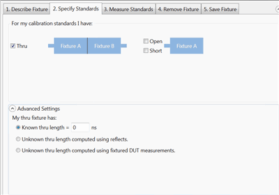
Note: The term 'Standards' is used here because this process can be thought of as the second in a '2-tier' calibration. The first tier of the calibration must already be performed (the VNA calibrated) before starting the AFR process. Another way of describing this step would be:

"How will you be measuring or loading the characterization of the Thru standard?"

  • Thru - Both halves together.

  • Both Thru halves separately. Specify either Open, Short, or Both at the end of each half of the standard.

Advanced Settings

This setting is used to describe any ADDITIONAL length between the halves of the Thru or added to either of the individual halves.

If the electrical length of the Thru standard is identical to the test fixture, then make no changes to the default settings (Known length = 0).

My Thru fixture has:

  • Known thru length - Enter the length in nanoseconds. See a simulated length in the diagram between the two halves of the Thru.

  • Unknown thru length computed using reflects.  This setting requires the two halves of the Thru fixture be characterized separately with a reflect standard.

  • Unknown thru length computed using fixtured DUT measurements.  This setting requires an additional characterization of the Fixture + DUT.


3. Measure Standards

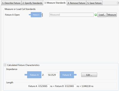
This step characterizes the Thru standards. This is done by either performing measurements or by loading one or more *.snp files that describe the characterization of the Thru standards.

Connect the standards and click Measure, or click Load and navigate to the *.snp file that describes the standard that is pictured.

Calculated Fixture Characteristics

The loaded or measured Impedance and Electrical Length of the fixture are calculated and displayed here.


4. Remove Fixture

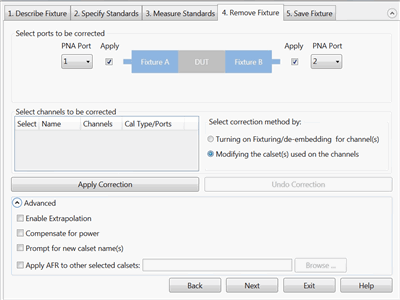
Note: First choose Select correction method, then make other selections, then click Apply Correction.

Both operations can be performed, but only one at a time.

  • Turning on Fixturing/de-embedding for channels. Usually only one channel is being used on the VNA, so only one channel will appear in the choices of channels to be corrected.  

    • Select the channels to be corrected.

      • Fixturing and de-embedding will be enabled for the selected channels in the VNA.

    • Advanced settings

      • Enable Extrapolation - When fixture data is loaded from a file and the frequency span of the data is not as wide as that of the channel, check this box to calculate and use linearly-extrapolated fixture data.

      • Compensate for power - When checked, test port power is increased to compensate for loss in the fixture.

  • Modifying the calset(s) used on the channels. Usually only one calset is in use on the VNA, so only one choice would be available.

    • Advanced settings

      • Enable Extrapolation - When fixture data is loaded from a file and the frequency span of the data is not as wide as that of the measurement, check this box to calculate and use linearly-extrapolated fixture data.

      • Compensate for power - When checked, test port power is increased to compensate for loss in the fixture.

      • Prompt for new calset names - When cleared, when you apply AFR to a calset, the calset is overwritten. Once done, this process is NOT reversible. When checked, you are prompted to enter a new calset name and the original is preserved. The new calset is written with AFR correction.

      • Apply AFR to other selected Calsets - When checked, allows you to apply AFR correction to other calsets not currently in use on the VNA. Click Browse, then navigate to the calsets to be corrected.


5. Save Fixture

Select File format to save fixture data:

    • Touchstone (*.snp)

    • Touchstone 2 (*.ts)

    • Citifile (*.cti)

Choose port assignment for save fixture files:

The port assignments are interpreted differently when the file is opened in each program.

Choose which program software you will be using to open the saved file: PLTS, VNA, ADS.


Choose the directory and base names for the saved files:

Click Browse to navigate to a directory folder.

With a base file name:  The resulting filename will appear as follows (assuming a Touchstone format):

  • <base file name>_1.S4P - The left half of a Differential fixture.

  • <base file name>_2.S4P - The right half of a Differential fixture.

  • <base file name>_1.S2P - The left half of a single-ended fixture.

  • <base file name>_2.S2P - The right half of a single-ended fixture.

Click Save Fixture Files to save the files to the specified directory.