This section shows a sample measurement procedure for impedance measurement.
Here is the typical steps.
Preparation
Setup an impedance measurement
Calibration at the 3.5 mm connector on the adapter box using 85052DH02
Place the 19168A fixture main body on the adapter box.
Fixture Compensation at the 16198A contact board.
Place your DUT on the 16198A contact board.
Make an measurement.
Prepare the required calibration kit, fixture and calibration data files. See Measurement Preparation.
On the VNA front panel, press Meas > S-Param > Meas Class....
Select Impedance Analysis, then either:
OK delete the existing measurement, or
New Channel to create the measurement in a new channel.
An Impedance
Analysis Setup is displayed. Set up your required settings,
then click OK or Apply.
Note: When the stop frequency is set
over 10 GHz, the calibration and fixture compensation cannot be executed.
Note: OSC Level (Power Level) should
be equal to or less than -16 dBm for the 16198A measurement.
If the adapter
box is connected with the port other than port 1. Select RF Rath tab. Then select VNA port
and click OK
If you want to setup the other parameters such as averaging, setup them from softkey.
Click Meas, then select your required impedance parameter.
Click
Format, then select your required
format according to the table below
Parameter |
Description |
Parameter in Meas softkey |
Format |
|Z| |
Absolute impedance |
Z |
Lin Mag |
θz |
Impedance phase |
Z |
Phase or Unwrapped Phase |
Z |
Impedance (complex value) |
Z |
Complex or Polar |
|Y| |
Absolute admittance |
Y |
Lin Mag |
θy |
Admittance phase |
Y |
Phase or Unwrapped Phase |
Y |
Admittance (complex value) |
Y |
Complex or Polar |
R |
Equivalent series resistance |
Z |
Real |
X |
Equivalent series reactance |
Z |
Imaginary |
G |
Equivalent parallel conductance |
Y |
Real |
B |
Equivalent parallel susceptance |
Y |
Imaginary |
Ls |
Equivalent series inductance |
Ls |
Real |
Lp |
Equivalent parallel inductance |
Lp |
Real |
Cs |
Equivalent series capacitance |
Cs |
Real |
Cp |
Equivalent parallel capacitance |
Cp |
Real |
Rs |
Equivalent series resistance |
Rs |
Real |
Rp |
Equivalent parallel resistance |
Rp |
Real |
Q |
Q value |
Q |
Real |
D |
Dissipation factor |
D |
Real |
If you need more traces for the other parameters, click Trace > New Trace..., then select the parameters your required. You can add/change the parameter after the calibration as well.
This procedure calibrate the 3.5 mm port on adapter box using 3.5 mm calibration kit. The Smart Cal is a wizard for calibration at 3.5 mm port and fixture compensation. The first page of Smart Cal defines both cal kit for 3.5 mm and fixture compensation for the 16198A in advance.
Click Cal > Cal Sets & Cal Kits > Cal Kit..., then Manage Cal Kit dialog box is displayed.
Click Import... , then select your 85052DH02 calibration data file.
Confirm that your 85052DH02 calibration kit is listed in the Standard Cal Kits.
Click Cal > Main > Smart Cal..., then Smart Cal dialog box is displayed.
Select your calibration kit from Cal Kit pull down menu.
Click "..." for Fixture Database and select your 16198A fixture calibration data file.
Specify fixture standard values for open and short compensations. Recommended values for 16198A open state is Open G: 0 S, Open C - 7.5 fF. For short bar: Short R: 0 ohm, Short L: 0.19 nH.
Click Next
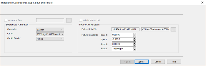
Import Cal from Choose Cal Sets file from "..." if you have a Cal Set with 85052DH02.
Import Fixture Cal from
S-Parameter Calibration 
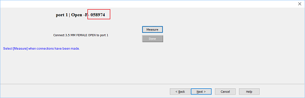
Connector Only 3.5 mm can be selected for the19198A. Cal Kit Select the calibration data which you imported at Cal Kit diaglog box. Cal Kit Gender Only female can be selected for the 19198A.
Fixture Compensation Fixture Data File Display the imported fixture calibration data file. Import the fixture calibration data file by clicking "...". 
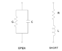
Fixture Standards Define the values for open/short standard values. Open Conductance (G), Open Capacitance (C), Shot Inductance (L) and Shot resistance (R). See the procedure above for the 16198A. Next > is not activated in the following conditions.
|
Connect 85052BH02 Open (f) on the 3.5 mm connector of the adapter
box. Confirm if the standard number is matched with one in the dialog
box.
Click Measure.
Click Next > after the open measurement is done.
Connect 85052BH02 Short (f) instead of Open.
Click Measure.
Click Next > after the short measurement is done.
Connect 85052BH02 Load (f) instead of Short.
Click Measure.
Click Next > after the load measurement is done.
The menu about open for fixture is displayed.
Align the 16198A test fixture with the adapter's mount post and 3.5-mm connector, then set it gently in place
Turn the adapter's 3.5-mm connector counterclockwise, connecting the bottom of the test fixture with the connector. The tightening torque used is 0.9 Nm.
Set the 16198A fixture at open state.
Click Measure.
Click Next > after the open measurement is done.
Set the required weight for pressure. The recommended weight for short bar is 200 to 300 g.
Place the short bar on the contact board. See the 16198A user's
guide in https://www.keysight.com/manuals/16198a
for details.
Set the 16198A at close state.
Click Measure.
Click Next > after the short measurement is done.
Click Save As User CalSet...
to save the calibration data into Cal Set file for future use.
Click Finish to finish the calibration and compensation for impedance analysis.
Remove the short bar.
Set your DUT on the contact board.
You can observe the measurement result on the screen.
To scaling in Log for Y axis, See Y-axis graph (Log Scale), Reference X Level, Reference X Position
Using Marker, See Markers.