Other topics about Measurement Wizard Assistant
The back-end application of the MWA is a program running on the VNA. The back-end application reads a spec sheet (.mwa) created by the MWA front-end application, and automatically sets up all the measurement parameters on the VNA. Based on the information included in the spec sheet,the back-end application sets up the VNA multiport test set, or the external peripherals,and executes measurement procedure the detailed analysis report of the results.
A method for starting the back-end application of the MWA on the VNA is explained below.
Press Macro > Macro 1 > MWA.
The back-end application of the MWA has the following windows:
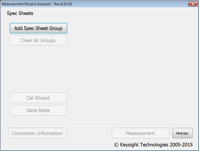
This is the first window displayed after startup.
In this window, the following buttons can be selected for enabling functionality available in the back-end application

Add Spec Sheet Group button (Main Window )
Displays Spec Sheet Setting Window.
Clear All Spec Groups button (Main Window )
Clears group files that have been already read in the Spec Sheet Setting Window.
Cal Wizard button (Main Window )
Displays Calibration Wizard Window (1/2)for automatic calibration procedure.
Save State button (Main Window )
Saves a status file on the VNA. As a status file is automatically saved in the VNA when saving a group file or the necessary calibration is completed in the Calibration Wizard Window, it is not necessary to press this button if the setting on the VNA is not changed.
Connection Information button (Main Window )
Displays Connection Information Window for verifying the connectivity of the network analyzer, the multiport test set, and the DUT.
Measurement button (Main Window )
Displays All Spec Sheet Measurement Window for launching measurement procedure.
Minimize button (Main Window )
Minimizes the window of the back-end application. This function provides easy access to the display of the VNA for changing parameters after recalling a spec sheet.
Spec Sheet List (Main Window )
The recalled group files with the list of spec sheets are displayed in the Main Window after the setup in the Spec Sheet Setting Window (link inserted). The name of spec sheets, the number of group files, and the allocated channel number of the VNA are included. The option button for each group file can be enabled for selecting the active group file used in the measurement.
If multiple spec sheets are bundled in a group file, the option button of the first sheet can be enabled for the group file (It is not necessary to select the other spec sheets).
The group with the circle mark (● ) on the option button is the current active group. The calibration performed in the Calibration Wizard Window and the measurement is effective for this active group. The state file is saved by the Save State button (Main Window ) for the active group file as well.
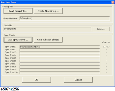
In this window, spec including all the parameters for the setup on the VNA are recalled. The multiple spec sheets are bundled into one group and handled as a group file (.ssg) in the following procedure of the back-end application. Up to 10 different spec sheets can be added in one group file.
Read Group File... button
Recalls a saved group file (.ssg).
An error occurs when power value is set to different value by VNA firmware.
In front-end application, the resolution of power value which can be set is 0.05dBm.
Create New Group... button (Spec Sheet Setting Window (x))
Creates a new group file (.ssg).
Browse... button (Spec Sheet Setting Window (x))
Displays the file selection dialog for status files of the group.
Add Spec Sheets... button (Spec Sheet Setting Window (x))
Adds a spec sheet (.mwa) under the group file. The default name of the group file is named after the recalled spec sheet.
Clear All Spec Sheets button (Spec Sheet Setting Window (x))
Clears all the spec sheets that have been already recalled in the window.
OK button (Spec Sheet Setting Window (x))
Reflects all the settings on the VNA according to the recalled spec sheets and returns to the Main Window. The state file for the group is saved automatically.
Cancel button (Spec Sheet Setting Window (x))
Discards the settings and returns to Main Window.
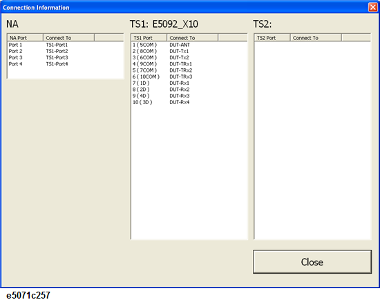
This window is displayed when Connection Information in the Main Window is selected.
Using the label names defined in the front-end application, this window shows information on the connection between the VNA, the multiport test set(s),and the DUT.
Close button
Closes the window and returns to the Main Window.
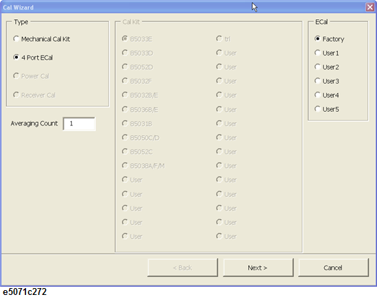
This window is displayed when Cal Wizard in the Main Window is selected.
The wizard provides the necessary steps of the calibration procedure with the VNA and the multiport test set in accordance with the contents of recalled spec sheets.
Calibration Wizard Window (1/2)
List of Calibration Types
Displays the calibration types that can be performed with the calibration wizard.
These include Mechanical Cal Kit (calibration with the mechanical calibration kit), 4-Port ECal (calibration with the 4-port ECal module), Source Power Cal and Receiver Power Cal (Receiver calibration).
Source Power Cal is applied only to the measurement paths whose Receiver frequencies in the spec sheet of front-end application has been filled.
List of Calibration Kits
Displays the list of mechanical calibration kits available on the VNA for the calibration. This can be selected when Mechanical Cal Kit is selected as the calibration type.
List of ECals
Displays the list of characteristics registered in the ECal modules. User-defined characteristics of the ECal module (User 1 to 5) can be selected for calibration with different types of connectors.
Averaging Count Entry
Sets the averaging number for measurements during calibration. This averaging number is used only during calibration and returns to the original number registered in the VNA when calibration is completed.
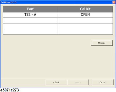
Calibration Wizard Window (2/2): mechanical calibration kit selected
Calibration Wizard Window (2/2): 4-port ECal selected
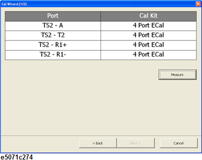
During execution of the calibration wizard, the port name in Port or the calibration standard in CalKit in Calibration Wizard Window may be grayed-out. This means "the connection between the port and the calibration standard is the same as step in calibration procedure"; therefore it is not necessary to disconnect the standards for the calibration measurement.
Measure button
Performs calibration measurement with the displayed connection.
<Back button
Goes back to the previous step in the Calibration Wizard.
Next > button
Goes to the next step in the Calibration Wizard after the calibration measurement is completed.
Cancel button
Aborts the Calibration Wizard and returns to the Main Window.
Done button (Cancel button changes)
Performs the correction of error coefficients on every necessary port then returns to Main Window.
Calibration data are automatically saved in the status file (.sta) of the group.
This window is displayed after the setup in the Lot Input Window when the Measurement button in the Main window is selected.
Spec sheets and summaries of their measurement results are listed in this window. To check the results by spec sheet, select each spec sheet in this window and press Manual Trigger.
All Spec Sheet Measurement Window
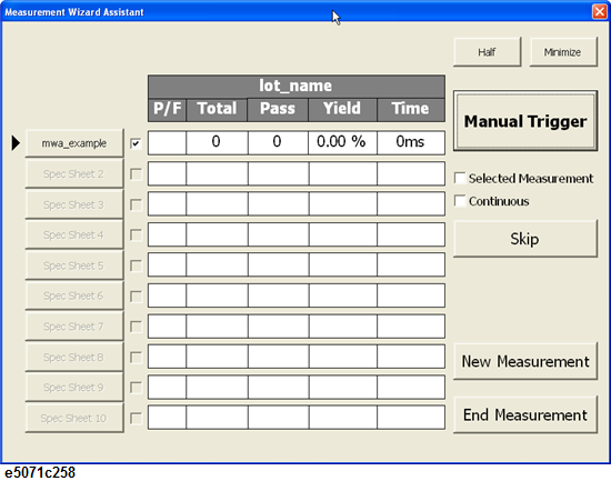
Spec Sheet button (All Spec Sheet Measurement Window (x))
Displays Measurement by Spec Sheet Window.
The spec sheet button with the black triangle icon to its left indicates the next sheet to be measured.
Measurement ON/OFF check box (All Spec Sheet Measurement Window (x))
Only the spec sheet with a checked mark is measured.
Half button
Rescale the Measurement Window of the back-end application with the half size of the screen. The window is located at the bottom half of the screen and the measurement results of the VNA is displayed in the top half. See the Measurement Window in half mode.
Minimize button
Minimizes the Measurement Window. See the minimized window.
Manual Trigger button
Makes an immediate measurements with manual trigger on the checked spec sheets in the window. (The black triangle icon is displayed to the left of the Spec Sheet button.)
Skip button
Skip the measurement of the spec sheet with a black triangle icon on the left.
New Measurement button
Ends measurement in the current window, saves the results, and displays All Spec Sheet Measurement Window with a new lot name.
End Measurement button
Ends measurement in the current window and returns to the Main Window. The measurement results are saved in the designated directory of the VNA.
This window is displayed by selecting one of the buttons for the spec sheets that are listed in the All Spec Sheets Measurement Window.
This window shows a list of the measurement modes in the selected spec sheet. To make measurements while checking measurement results in different measurement modes, press Manual Trigger in this window.
Measurement by Spec Sheet Window
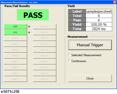
Manual Trigger button (Measurement by Spec Sheet Window (1))
Makes an immediate measurement with manual trigger on the checked spec sheets in the All Spec Sheets Measurement window.(The same function on the Manual Trigger button in the All Spec Sheets Measurement Window).
Close button (Measurement by Spec Sheet Window (1))
Returns to the All Spec Sheet Measurement window.
This window is displayed by selecting one of the buttons for the measurement modes listed in the Measurement by Spec Sheet Window.
This window shows a list of measurement results for the measurement paths specified in the selected measurement mode.
Results Verification by Mode Window
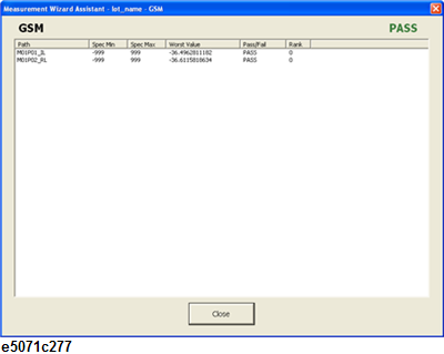
Measurement results display area
Path: The label name of a measurement path that is defined in the "Spec Sheet" in the front-end application.
Spec Min/Max: The maximum and minimum limit values of the DUT specification for the measurement paths. These values are entered in the "Spec Sheet" in the front-end application.
Worst Value: The limit test by the back-end application is performed for each measurement point and the worst value of the DUT is displayed in the measurement result. The worst value is defined as the farthest value from the average of the maximum and minimum limit values, which corresponds to the typical measured data of the DUT.
Pass/Fail: Indicates the result of the limit test for all data in the measured path.
Rank: The rank value of each measurement path (specified in the Spec Sheet sheet in the front-end application). The result of the limit test can be prioritized and sorted in all the measurement paths with the fail. The back-end application outputs the minimum rank value among the failed measurement paths. For example, by assigning the smallest rank value for a specific measurement path, you can identify the worst performance of the DUT with the output of the rank value after the measurement.
If the result of the limit test gives pass for all the measurement paths, the output rank value is "0".
The definition of the pass/fail result of the measurement can be ranged by the Max Fail Rank specified in the Lot Input Window of the back-end application. When the rank value is greater than the max fail rank value, the failed result of the limit test is treated as pass, and the corresponding rank values for measurement paths are outputted in the result. The following table shows an example of the output rank values, when (the Max Fail Rank is set to 200).
|
Rank value for path |
Pass/Fail |
Rank to be output |
|
1 - 200 |
Fail |
1 - 200 |
|
201 - 255 |
Pass |
201 - 255 |
For the measurement value, Worst Value, and Pass/Fail judgment, refer to step10 of the Setting Up Measurement Parameters in Each Mode.
Close button
Returns to Measurement by Spec Sheet Window.
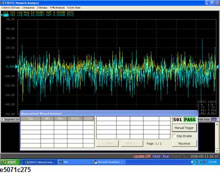
Measurement Window in Half mode: This window is shown when half in the All Spec Sheets Measurement Window is pressed.
You can use this window when you want to use the MWA while watching the measurement result displayed in the screen of the VNA. In this window, only a failed measurement path is displayed and you can check the corresponding channel and trace for further investigation of the result.
If the measurement paths cannot be displayed in one screen, the <<Prev button and the Next>> button become effective.
If you check the Disp enable check box, Display Update function of VNA is activated for drawing the image on the screen. It is recommended to disable this function and save time for updating the display when the fast testing speed is really required.
Measurement Window in Half Mode
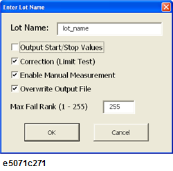
The lot input window is used for the setup of the measurement. For more information, refer to the Measurement Procedure (All Spec Sheets Measurement Window).
The procedure described below is for selecting or clearing spec sheets in the Main Window or in the Spec Sheet Setting Window.
Press Add Spec Sheet Group in the Main Window to display the Spec Sheet Setting Window.
To create a new group, press Create New Group... in the window, type the name of the new group in the file dialog, and press Save.
To recall an existing group, press Read Group File... in the window, select the group file in the file dialog and press Open.
The full path name of the group file entered or selected is displayed in the window
To specify the state file to be associated with the group, press Browse... in the State File frame, select the state file to recall and press Open.
The full path name of the selected state file is displayed in the window.
Press Add Spec Sheets... in the window. Select the spec sheet to use in measurements and press Open.
The name of the selected spec sheet and allocated channel numbers in VNA will be displayed in the window.
To select multiple spec sheets, repeat Step 4 as many times as needed to read all necessary spec sheets.
When you select a spec sheet without selecting a group file or a status file, the displayed names of these files are the same as that of the spec sheet.
If an error message appears, refer to Error messages in the Back-End Application.
After selecting all the necessary spec sheets, press OK to return to the Main Window. The name of the spec sheet and the allocated channel information will be displayed in the Main Window.
All the functions in the Main Window become available after the spec sheet is imported in the back-end application.
When no spec sheet is imported or all the spec sheets are cleared by Clear All Groups, the buttons in the Main Window are Disabled and the related their functions become unavailable.
Select Clear All Groups in the Main Window after setting up the group file in the Spec Sheet Setting Window.
All the group files are cleared and all the buttons in the Main Window become Disabled and the related functions become unavailable.
It is not available to clear each group file individually.
The procedure described below is for checking the connection between the measurement instruments and the DUT in the Connection Information Window.
Select Connection Information in the Main Window after recalling a spec sheet.
The Connection Information Window is displayed. Based on the information on the screen, connect the cables between the VNA, the multiport test set(s) and the DUT.
After checking that the connection is correct, press Close to close the window and return to the Main Window.
The connection should be confirmed before the calibration procedure in the Calibration Wizard Window. It is also recommended to check the connection again before starting the measurement in the Measurement Window.
The procedure described below is for performing the calibration procedure by the Calibration Wizard Window of the back-end application.
Select a group file to calibrate with the radio button in the Main Window.
Select Cal Wizard in the Main Window.
The calibration wizard starts up and the Calibration Wizard window (1/2) is displayed. From the list of types of calibration shown in the window, select the type of calibration to perform. The following options are available:
|
Type of Calibration |
Description |
|
Mechanical Cal Kit |
Uses a calibration kit to perform calibration. For information on the selecting a calibration kit, refer to Step 4. |
|
4 Port ECal |
Uses 4-port ECal to perform calibration. |
|
Receiver Cal |
Performs Receiver calibration while making FOM measurements. |
If Mechanical Cal Kit is selected in Step 3, the list of calibration kits available for selection is displayed in the window. Select the appropriate calibration kit to use.
If 4-port Ecal has been selected in Step 3, the list of user-defined characteristics of the ECal module is displayed in the window. Select the appropriate characteristics of the ECal module to use. Refer to User-characterized ECal for more detail.
Note: The information on displayed calibration kits has been imported from the VNA firmware. When the parameters of the calibration kit are changed in the VNA, corresponding information will be reflected in the back-end application as well.
Enter the number of averaging during the calibration measurement into the Averaging Count input box. All the parameters on the calibration kit are selected, press Next for the next step in the calibration procedure.
The Calibration Wizard Window (2/2) will be displayed. Both the ports of the VNA or the multiport test set and the calibration standards used for the calibration are displayed. Connect the ports with the standard and press Measure. After the calibration measurement is completed, press Next > for the next step.
Repeat Step 6 as many times as needed for all the calibration steps necessary for the selected spec sheets. After all the calibration measurement is completed, press Done and return to the Main Window. The Calibration data will be saved in the state file of the selected group file automatically.
When performing calibration with ECal,the MWA back-end application shows "Execution error" if active channel is selected for trigger scope on the VNA firmware. Hence, select All Channels for the trigger scope.
The procedure for saving state files in the Main Window is described below.
The State file for a group is automatically saved when you create a group file in the Spec Sheet Setting Window or you perform calibration in the Calibration Wizard Window. If parameters on the VNA are changed without using the functions of the back-end application, a state file should be saved manually in the Main Window.
Press Save State in the Main Window.
The State Files (.sta) of the current active groups are updated.
The procedure described below is for making measurements by spec sheet in the All Spec Sheets Measurement Window.
After the setup of spec sheets in the Spec Sheet Setting Window, press Measurement in the Main Window. The lot Input Window is displayed.
Enter the lot name of the DUT. Check optional functions in the measurement as necessary and press OK.
Output Start/Stop Values
This option allows you to write measured values at the start and stop frequencies to a result file of the measurement. The back-end application automatically generates the result file for each spec sheet after the measurement. Refer to Measurement result by spec sheet.
Correction (Limit Test)
This option allows you to reflect the correction on measured values specified in the “Spec Sheet” front-end application, refer to Step 9 in the Setting Measurement Parameters in Each Mode.
Enable Manual Measurement
This option enables the Manual Trigger button in the All Spec Sheets Measurement Window and the Measurement by Spec Sheet Window. When this option is not checked, manual measurements using the Manual Trigger button cannot be made.
Overwrite Output File
This option allows you to overwrite or add the measurement result when a result output file already exists. When this option is checked, the existing file is overwritten.
Max fail rank (1-255)
This option sets the maximum rank value for the fail result in the limit test. For example, when "max fail rank" is set to 10, the result for measurement paths with ranks 1 through 10 treated as fail and 11 through 255 treated as pass. For more information, refer to rank in Measurement results display area.
When you press the OK button, the All Spec Sheet Setting Window is displayed.
Press Skip to place the black triangle icon to the left of the desired spec sheet with which measurements are made.
With the black triangle icon placed to the left of the spec sheet for use during measurement, press Manual Trigger to perform measurement.
To do the measurement for the selected measurement paths that have been checked in the "Spec Sheet” of the front-end application, check Selected Measurement and press Manual Trigger.
To make consecutive measurements using the displayed spec sheets, check the Continuous check box.
When measurements for the spec sheets are completed, the measurement result (Pass or Fail) is displayed to the right of each spec sheet.
Note: To check measurement result for each spec sheet, press the button of the desired spec sheet to display the Measurement by Spec Sheet Window. For information on the Measurement by Spec Sheet Window, refer to Measurement Procedure (Measurement by Spec Sheet Window).
The procedure described below is for selecting one of the spec sheets in the measurement window, and making detailed measurement in the Measurement by Spec Sheet Window for each measurement mode included in the spec sheet.
In the All Spec Sheets Measurement Window, press the button of the desired spec sheet to display the Measurement by Spec Sheets Window for the spec sheet.
Press Manual Trigger to launch the measurement for each mode in the selected spec sheet.
To do the measurement for the selected measurement paths that have been checked in the Spec Sheet” sheet of the front-end application, check the box for Selected Measurement and press Manual Trigger.
To make consecutive measurements with continuous sweep for all the measurement modes, check the Continuous check box.
When measurements are completed, the letter "P" (for Pass) or "F" (for Fail), is shown to the right of the measurement mode. Press Close, to return to the All Spec Sheets Measurement Window.
Note: To check detailed measurement results for each measurement mode, press the button for the desired measurement mode to display the Results Verification by Mode Window. For information on the Results Verification by Mode Window, refer to Measurement Procedure (Results Verification by Mode Window).
The procedure described below is for selecting one of the measurement modes and checking results by measurement path in the Results Verification by Mode Window.
To display the Results Verification by Measurement Mode Window, press the button of the desired measurement mode in the Measurement by Spec Sheet Window.
Measurement results for each measurement path are listed in the Results Verification by Measurement Mode Window. For more details in the listed parameters, refer to measurement results display area in the Results Verification by Mode Window.
This section describes measurement result files that are created at the end of a measurement.
Measurement result summary by lot
This file is created at the end of a measurement or when the name of a lot is changed by selecting New Measurement in the All Spec Sheets Measurement Window. It is created in csv format and saved automatically in the VNA.
The content of the created file is shown in Measurement result summary by lot.
Measurement result summary by lot
The first line is the header of a file and the second line or below contains the measurement result for each spec sheet. The following parameters are included in the result:
Spec Sheet x: The name of a spec sheet used in the measurement.
Total Number: The total number of the measurement for the lot of the DUT.
Pass Number: The total number of the pass result for the lot of the DUT.
Mode x: The label name of the mode in a spec sheet that gives the fail result in the measurement.
Mode x Fail Number: The total number of the fail result for the mode in a spec sheet.
Measurement result by spec sheet
The file of measurement result is created separately for each spec sheet. Each file is created in csv format ("Lot name"-"spec sheet name".csv) and saved automatically in the same folder as each spec sheet (.mwa) of VNA. The content of the created file is changed depending on the selection of the “output start/stop value” check box in the Lot Input Window.
The content of the created file is shown in Measurement result by spec sheet.
Files of measurement results by spec sheet (start/stop value: ON)
|
"Index","Rank","Mode1-Path1",,,"Mode1-Path2",,,"[GPIB**Address] GPIB Command, ... ,"ModeX-PathY",, ,,"Start","Stop","Worst", ... ,"Meas", ... ,"Start","Stop","Worst", ... 1,Output Rank,Start_Value,Stop_Value,Worst_Value, ... ,GPIB_Response Value, ... ,Start_Value,Stop_Value,Worst_value, ... 2,Output Rank,Start_Value,Stop_Value,Worst_Value, ... ,GPIB_Response Value, ... ,Start_Value,Stop_Value,Worst_Value, ... ... N,rOutput Rank,Start_Value,Stop_Value,Worst_Value, ... ,GPIB_Response Value, ... ,Start_Value,Stop_Value,Worst_Value, ... |
The first and second lines are the header of a file, and the third line or below contains all the measurement result for the spec sheet. The following parameters are included in the file:
Index: The number of measurement for the spec sheet.
ModeX-PathY: The tag namme of the measurement path for the specific mode in a spec sheet.
Output Rank: The output rank value for the spec sheet. See Rank for the details.
Start Value: The measured value at the start frequency for the measurement path.
Stop Value: The measured value at the stop frequency for the measurement path.
Worst Value: The worst value in the measured frequency range for the measurement path. See Worst Value for the details.
GPIB Response Value: The measured value that is imported from an external peripheral by a GPIB command. The result value is inserted at the end of results for a measurement mode. The query command is shown in the header with the GPIB address of the used peripheral.
All the measurement values of a single DUT are summarized in one line. When multiple measurements are performed for a spec sheet, the multiple measurement results in additional lines are included in the file.
As the measurement value at the start/stop frequency is not available for the measurement type such as “mean” or “ripple”, no data is recorded in the start/stop values for the path.
Note: Even when the measurement for a spec sheet is skipped by the Skip button in the All Spec Sheets Measurement Window, the result is recorded in the file as well. However, the output rank is fixed to -1 and no measured values are recorded for the start/stop or worst values.
When "Output Start/Stop value" is disabled by the Lot Input Window in advance of the measurement, the contents of the output is shown below:
Measurement result by spec sheet (start/stop value: OFF)
|
"Index","Rank","Mode1-Path1",,,"Mode1-Path2",,,"[GPIB**Address]GPIB Command", ... ,"ModeX-PathY",, 1,Output Rank,Worst_value, ... ,GPIB Response Value, ... ,Worst_Value, ... 2,Output Rank,Worst_value, ... ,GPIB Response Value, ... ,Worst_Value, ... ... N,Output Rank,Worst_value, ... ,GPIB Response Value, ... ,Worst_Value, ... |
The procedure for controlling the back-end application from an external PC is described below.
Send the following commands to the VNA via GPIB.
DISP:WIND1:TITL:DATA (Command Parameter)
The following command parameters are available with the MWA.
Command Parameter
|
cmd_para function |
Argument 1 |
Argument 2 |
Window that accepts the command |
|
cmd_read |
Group file name (.ssg) or spec sheet name (.mwa) |
|
Main Window |
|
cmd_clear |
- |
|
Main Window |
|
cmd_begin |
Lot name |
Parameters in the Lot Input Window. For more details, refer to Measurement Procedure (All Spec Sheets Measurement Window) |
Main Window, Measurement Window |
|
cmd_initiate |
- |
|
Measurement Window |
|
cmd_skip |
- |
|
Measurement Window |
|
cmd_settings |
Correction values, Manual measurement |
|
Measurement Window |
|
cmd_end |
- |
|
Measurement Window |
Each of the cmd_para functions as follows.
|
cmd_para functions |
Description |
Corresponding buttons |
|
cmd_read |
Reads the group file or spec sheets specified by the argument 1. If you send this command when no file exists or no more files can be read, an error occurs. To specify multiple spec sheets, specify spec sheets separated with commas when assigning an argument 1 in Step 2. |
Main Window Add Spec Sheet Group |
|
cmd_clear |
Clears all spec sheets that are currently read. |
Main Window Clear All Groups |
|
cmd_begin |
Displays the All Spec Sheets Measurement Window, specifying a lot name of the DUT by using argument 1. Argument 2 specifies the option for the measurement (the same setup in the Lot Input Window). For more details, refer to Measurement Procedure (All Spec Sheets Measurement Window). For each option, refer to that page.
The same as Start/Stop values. Specifies 0 (OFF) or 1 (ON).
The same as Correction (Limit Test). Specifies 0 (OFF) or 1 (ON).
The same as enable Manual Measurement. Specifies 0 (OFF) or 1 (ON).
The same as Overwrite Output File. Specifies 0 (OFF) or 1 (ON).
The same as max fail rank (1-255). Specifies the value from 1 to 255. If you send this command when each measurement window is displayed, a summary of the results is generated to a file, the current measurement is closed, and the All Spec Sheets Measurement window opens with a new lot name. |
Main Window Measurement All Spec Sheets Measurement Window New Measurement |
|
cmd_initiate |
Initiates measurement immediately. |
All Spec Sheets Measurement Window Manual Trigger Measurement by Spec Sheet Window Manual Trigger |
|
cmd_skip |
Skips the measurement of the next spec sheet. |
All Spec Sheets Measurement Window Skip |
|
cmd_settings |
Changes the option of correction values and manual measurement during the measurement. For correction values and manual measurement, refer to the descriptions of cmd_begin. |
None |
|
cmd_end |
Outputs summary of the results and returns to the Main Window. |
All Spec Sheets Measurement Window End Measurement |
If it is necessary to set the argument for a command, the following command is required before sending the command in Step 1. If each argument has several items, set all the parameters separated by a comma (,).
Setting command of Argument 1
DISP:WIND2:TITL:DATA parameter
Setting command of Argument 2
DISP:WIND3:TITL:DATA parameter
For example, to start new measurement using the lot name "lot_gsm001," send the following command. In the following example, the output start/stop value and overwrite output file are turned ON and the max fail rank is set to 100.
10 output 717;"DISP:WIND2:TITL:DATA lot_gsm001"
20 output 717;"DISP:WIND3:TITL:DATA 1,0,0,1,100"
30 output 717;"DISP:WIND1:TITL:DATA cmd_begin"
Note: If you send a command with incorrect arguments, the command is not executed.
When the command process finishes, the return value of DISP:WIND1:TITL:DATA? becomes "cmd_done" If you want to wait for the command process to finish, confirm this by whether the returned value of DISP:WIND1:TITL:DATA? is "cmd_done"
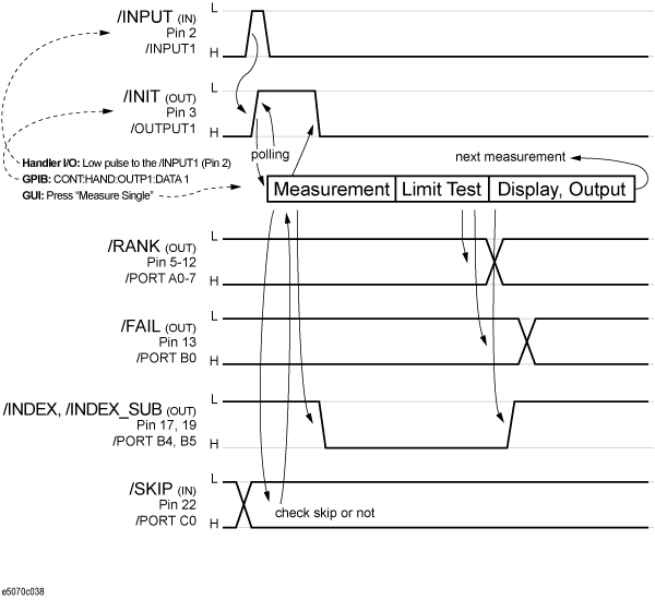
A list of pins of the handler I/O operated by the MWA is shown below. The signal notations in the parentheses correspond to those of the VNA. For details, refer to I/O Signal Pin Layout and Description.
|
Pin number |
Signal Name in MWA (signal name in normal mode) |
Direction of signal |
Description |
|
2 |
/INPUT (/INPUT1) |
Input |
When a negative pulse is applied to this pin, the level of the signal /OUTPUT1 becomes Low. |
|
3 |
/INIT (/OUTPUT1) |
Output |
When a negative pulse is applied to pin 2, the level of /OUTPUT1 becomes Low. The back-end application monitors /OUTPUT1 and when it turns Low, starts measurement. /OUTPUT1 returns to High at the start of a measurement. In addition, the "CONT:HAND:OUTP1:DATA 1" command can be used to set the signal level to Low or High. |
|
5 |
/RANK A0 (/PORT A0) |
Output |
Outputs the minimum rank value for the measurement. The output rank is the 8-bit value (0-255) with A0 as LSB and A7 as MSB. /PORT A0 is bit 0 of the output rank. |
|
6 |
/RANK A1 (/PORT A1) |
Output |
Bit 1 of the output rank. |
|
7 |
/RANK A2 (/PORT A2) |
Output |
Bit 2 of the output rank. |
|
8 |
/RANK A3 (/PORT A3) |
Output |
Bit 3 of the output rank. |
|
9 |
/RANK A4 (/PORT A4) |
Output |
Bit 4 of the output rank. |
|
10 |
/RANK A5 (/PORT A5) |
Output |
Bit 5 of the output rank. |
|
11 |
/RANK A6 (/PORT A6) |
Output |
Bit 6 of the output rank. |
|
12 |
/RANK A7 (/PORT A7) |
Output |
Bit 7 of the output rank. |
|
13 |
/FAIL (/PORT B0) |
Output |
If the limit test fails, /PORT B0 becomes enabled (Low level). If the output rank value (/PORT A0 - /PORT A7)is 0 (which corresponds to the pass for all measurements), /PORT B0 becomes disabled (High level). This signal transits after the output /RANK (/PORT A0 to A7) transition, but transits almost the same timing of the /INDEX (/PORT B4) transition. Be sure to check /FAIL with some delay after /INDEX transition. |
|
17 |
/INDEX (/PORT B4) |
Output |
A signal that indicates the end of measurement. The signal transits after the output rank (/PORT A0 - /PORT A7) transition. The back-end application sets /PORT B4 back to inactive (High level) at the start of measurement. |
|
19 |
/INDEX_SUB (/PORT B5) |
Output |
A reserved signal pin with the same function as /PORT B4. Either pin can be used. |
|
22 |
/SKIP (/PORT C0) |
Input/Output |
This is a skip signal. If /PORT C0 is enabled (Low level) before measurement, the measurement is not performed and the status shifts to the mode of waiting for the next measurement. |
While working with MWA, an error message may appear due to improper VNA settings. This section explain the various error messages and the method to avoid these errors.
|
Error Message |
Description |
|
Channel Max |
This error message appears if the total number channels required for a spec sheet (.mwa) is more than the number of channels set in the VNA. Note: This error can be avoided by increasing the maximum number of channels in VNA. |
|
Configuration and test set are mismatched. |
This error message appears if the configuration of the test set specified in a spec sheet (.mwa) generated by the Front-End Application is different from the test set that is being connected to the VNA. This error can be avoided by changing the configuration of the Multiport Test Set sheet in the Front-End Application. For more info, refer to Selecting Test Set.
This error may appear if:
|
|
GPIB Error |
This error message appears if the GPIB address of peripherals connected to the VNA is different from what you specified in the GPIB sheet of the front-end application. |
|
Invalid number of point |
This error message appears if the maximum number of points required for a spec sheet (.mwa) is more than the number of points set in the VNA. Note: This error can be avoided by increasing the maximum number of channels in VNA. |
|
Invalid Trace |
This error message appears if the maximum number of traces required for a spec sheet (.mwa) is more than the number of traces set in the VNA. Note: This error can be avoided by increasing the maximum number of channels in VNA. |