Other Measurement Setup Topics
Check out the Integrated True Mode Stimulus Application (iTMSA).
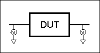
Standard Single-ended devices generally have one input port and one output port. Signals on the input and output ports are referenced to ground.

Balanced devices have two pins on either the input, the output, or both. The signal of interest is the difference and average of the two input or output lines, not referenced to ground.
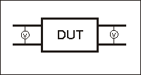
On balanced devices, the signal of interest is the difference and average of the two input or output lines. In balanced device terminology, these signals are known as the Differential and Common modes.
The following model shows how two signals (A and B) combine to create Differential and Common mode signals:
Signal A is fixed at 1V peak
Signal B is selectable
Differential is calculated as A minus B
Common is calculated as the AVERAGE of A and B
Note: Click Signal B selections to see various Differential and Common signals.
Signal A =1V |
|
|
|
|
|
Differential
|
Common (Avg)
|
|
|||
Signal B = SELECTABLE |
Calculations |
||
Single-ended0V |
1 - 0 = 1 |
(1 + 0)/2 = .5 |
|
180° Out of Phase.1V |
1 - (-1) = 2 |
(1 + (-1))/2 = 0 |
|
180° Out of Phase 2V |
1 - (-2) = 3 |
(1 + (-2))/2 = -.5 |
|
In Phase 1V |
1 - 1 = 0 |
(1 + 1)/2 = 1 |
|
In Phase 2V |
1 - 2 = -1 |
(1 + 2)/2 = 1.5 |
|
Notes:
Even when Signal B is 0V, like a Single -ended signal, there is still a unique Differential and Common mode representation of the two individual signals.
The above model does not show a DUT. The difference and average of two signals can be calculated for both the balanced INPUT and balanced OUTPUT of a device.
Mixed mode S-parameters combine traditional S-parameter notation with balanced measurement terminology.
Some balanced devices are designed to amplify the differential component and reject the common component. This allows noise that is common to both inputs to be virtually eliminated from the output. For example, a balanced device may amplify the differential signal by a factor of 5, and attenuate the common signal by a factor of 5. Using traditional S-parameter notation, an S21 is a ratio measurement of the device Output / device Input. Mixing this with balanced terminology, we could view the amplifier's Differential Output signal / Differential Input signal. To see this parameter on the analyzer, we would select an Sdd21 measurement using the following balanced notation:
Sabxy -
Where
a - device output mode
b - device input mode
(choose from the following for both a and b:)
d - differential
c - common
s - single ended
x - device output "logical" port number
y - device input "logical" port number
Imbalance is a measure of how well two physical ports that make up a balanced port are matched. With a perfectly balanced port, the same amount of energy flows to both ports and the magnitude of the ratio of these ports is 1.
The notation is similar to traditional S-parameters. In the following diagrams, the letters a, b, c, and d are used because any analyzer port can be assigned to any logical port using the port mapping process.
For example, in the following single-ended - balanced formula, Sba indicates the device output port is logical port b and the input port is logical port a.
Imbalance parameter when measuring a balanced device. |
Imbalance parameter when measuring a single-ended - balanced device.
|
Imbalance parameter when measuring a balanced - single-ended device.
|
Imbalance1 and Imbalance2 parameters when measuring a balanced - balanced device.
|
Imbalance1 and Imbalance2 parameters when measuring a single-ended - single-ended - balanced device.
|
CMRR is a ratio of the transmission characteristic in differential mode over the transmission characteristic in the common mode of the balanced port as the measurement parameter. A high value indicates more rejection of common mode, which is desirable in a device that transmits information in the differential portion of the signal. The table below shows the CMRR parameter you can select when measuring each balanced device.
Single-ended - balanced device |
Sds21 |
and |
Ssd12 |
Balanced - single-ended device |
Ssd21 |
and |
Sds12 |
Balanced - balanced device |
Sdd21 |
|
|
Single-ended - single-ended - balanced device |
Sds31 |
and |
Sds32 |
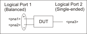
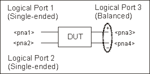
As we have seen on balanced inputs and outputs, the signal of interest is the difference or average of two BALANCED input or BALANCED output lines. It is also possible to have single-ended ports AND balanced ports on the same device. The two balanced input or output lines are referred to as a single "logical" port.
When configuring a balanced measurement on the analyzer, select a device 'topology'. Then map each test port to the DUT ports. The analyzer assigns "logical ports". See how to set device topology.

The following device topologies can be measured by a 4-port analyzer.
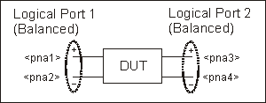
Balanced / Balanced
(2 logical ports - 4 physical ports)
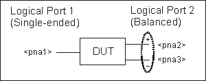
Single-ended
/ Balanced
(2 logical ports - 3 physical ports)
Balanced
/ Single-ended
(2 logical ports - 3 physical ports)
Single-ended
- Single-ended / Balanced
(3 logical ports - 4 physical ports)
These topologies can be used in the reverse (<==) direction to measure:
Balanced / Single-ended topology
Balanced / Single-ended - Single-ended topology
For example, to measure a Balanced / Single-ended topology, measure the S12 (reverse direction) of a Single-ended / Balanced topology.
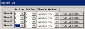
Balanced measurements are calibrated in the same manner as single-ended (standard) measurements. However, for highest accuracy, you must choose Thru paths so that each transmission path of the balanced measurement is represented. For a Balanced/Balanced topology, this means that FOUR Thru connections should be made.
For example (see following image):
Balanced Port 1 is ports 1 and 3
Balanced Port 2 is ports 2 and 4
Thru paths to be calibrated should be: 12, 14, 32, 34.
Paths 13, and 24 are less important.

To select Thru paths:
From SmartCal, on the Select DUT Connectors and Cal Kits page, check Modify Cal.
Click Next to see the following Cal Wizard page:
When using standard Balanced measurements, the analyzer does not provide true balanced measurements by stimulating both balanced inputs together and measuring both outputs relative to one another. Instead, the analyzer makes only Single-ended measurements. On a Balanced/ Balanced device, it stimulates each input and measures each output individually. From the output data, the analyzer calculates the Differential and Common outputs from the DUT using the math formulas below. However, all measurements and calculations are performed in frequency domain using complex (magnitude and phase) data. The Balanced S-parameter display data is then calculated from the Differential and Common inputs and outputs.
In iTMSA, the VNA DOES stimulate both balanced inputs with true balanced sources.
Differential to Differential
Sdd11=0.5*(S11-S21-S12+S22)
Sdd12=0.5*(S13-S23-S14+S24)
Sdd21=0.5*(S31-S41-S32+S42)
Sdd22=0.5*(S33-S43-S34+S44)
Common to Differential
Sdc11=0.5*(S11-S21+S12-S22)
Sdc12=0.5*(S13-S23+S14-S24)
Sdc21=0.5*(S31-S41+S32-S42)
Sdc22=0.5*(S33-S43+S34-S44)
Differential to Common
Scd11=0.5*(S11+S21-S12-S22)
Scd12=0.5*(S13+S23-S14-S24)
Scd21=0.5*(S31+S41-S32-S42)
Scd22=0.5*(S33+S43-S34-S44)
Common to Common
Scd11=0.5*(S11+S21+S12+S22)
Scd12=0.5*(S13+S23+S14+S24)
Scd21=0.5*(S31+S41+S32+S42)
Scd22=0.5*(S33+S43+S34+S44)