Last Updated: August 29, 2007
The Midplane board has a number of diagnostic LEDs that are visible when the outer cover is removed.
The table below lists the Power Supply Diagnostic LEDs. When the Power Supply is operating correctly the diagnostic LEDs will match the conditions indicated in the table.
|
LEDs (Stand-By) |
LEDs (Test Set On) | |
|
+15.0VA |
Red |
Off |
|
+9.0VA |
Red |
Off |
|
+3.3VA |
Red |
Off |
|
+5.2VA |
Red |
Off |
|
+15VSB |
Green |
Green |
|
+32VA |
Red |
Off |
|
-12VD |
Red |
Off |
|
-15VA |
Red |
Off |
|
-5.2VA |
Red |
Off |
|
-7.0VA |
Red |
Off |
|
+5.1VSB |
Green |
Green |
|
+12VD |
Red |
Off |
|
+3.35VD |
Red |
Off |
|
+5.1VD |
Red |
Off |
|
POWER OK |
Red |
Off |
|
POWER ON |
Off |
Green |
VA = Voltage Analog
VD = Voltage Digital
VSB = Voltage Stand By
|
|
The +15V Stand-By powers the oven controlled oscillator for 10 MHz Timebase Reference, ambient temperature sensor, power temperature shut-down circuit and the fan speed control voltage circuit. This supply is active when the test set is connected to an AC source. 
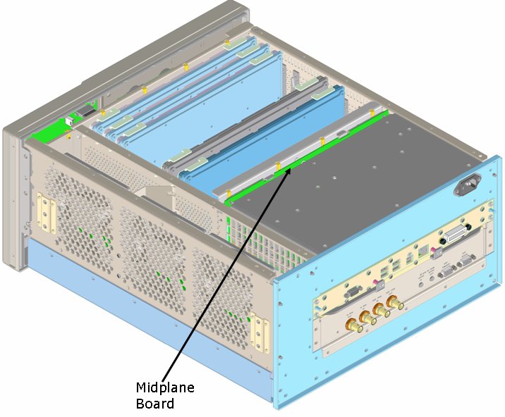
The +5.1 V Stand-By powers the Advanced Configuration and Power Interface of the PC Processor, the standby power indicator on the front panel and the Power Supply Diagnostic LEDs on the Midplane Board. This supply is active when the test set is connected to an AC source. |
