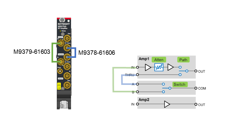
The M9379A consists of the following components.
The specification of each component is described in the data sheet.
When connecting or disconnecting a cable to the module, do not touch the open end of the cable. Doing so may damage the module by electrostatic discharge (ESD).
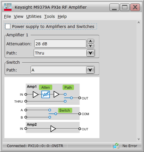
Power supply to Amplifiers and Switches: Master switch for amplifiers both 1 and 2 and switches.
LED on the front panel is changed as follows.
ON: Light green
OFF: Dark green
45-minute warm up time after this switch on is required to meet the specification accuracy.
The module temperature should be within the specified range to meet the specification accuracy. See Selftest in Utilities Menu to check the module temperature. See the data sheet for accuracy and the specified temperature range.
Amplifier 1
Attenuation: Attenuator setting for the amplifier 1. This can be set from 0 to 28 dB with 2 dB step.
Path: Path for amplifier 1. Thru or Amp
Switch
Path: Path for switch. A or B
The two semi-rigid cables are furnished with the M9379A. The example of connections are shown below.