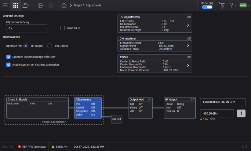
This topic describes the parameters of the ![]() Adjustments block.
Adjustments block.
Optimization for RF Output/External IQ Output
Optimize Dynamic Range with OBW
For M9484C Option AN1 is required.
Enables the internal optimized path to accommodate I/Q signals.
I/Q Ouput (EXTernal): applies correction terms to provide a calibrated signal at the IQ output. When I/Q Output is selected, the RF signals at the RF Output are uncalibrated.
RF Output: Applies correction terms to provide a calibrated signal at the RF output. When the RF Output is selected, the I/Q signals at the I/Q Output are uncalibrated.
|
GUI Location |
Adjustments > Optimize for RF Output | I/Q Output |
|
SCPI Command |
[:SOURce]:IQOut<channel>:CORRection:OPTimization:DESTination RFOut|EXTernal [:SOURce]:IQOut<channel>:CORRection:OPTimization:DESTination? |
|
SCPI Example |
IQO:CORR:OPT:DEST RFO IQO:CORR:OPT:DEST? |
|
Notes |
For M9484C without Option AN1, error 703 Feature not supported; Option AN1 not installed occurs. |
|
Preset |
RFO |
|
Choices |
RF Output | I/Q Output |
|
State Saved |
Yes |
|
Initial S/W Revision |
A.01.00 |
Enables the optimization based on occupied bandwidth (OBW).
This feature filters the system RF flatness correction coefficients over the instantaneous bandwidth, indicated in the waveform header, or in the Waveform File Occupied Bandwidth GUI field. This has the potential to improve EVM performance by not having to correct for flatness errors outside the requested bandwidth. For example, if the maximum optioned bandwidth is 2 GHz, but your signal is 800 MHz wide and centered, then flatness corrections will ignore any adjustments that would be needed to flatten the 600 MHz bands on either side of your signal. This can reduce the dynamic range consumed by the flatness correction, improving signal to noise ratio and EVM at frequencies where the unused bands have significant roll off.
When multiple signals are enabled, with M9484C Option 8SG, the combined occupied bandwidths are used to determine the minimum and maximum points of the extent of corrections. In other words, any "holes" in the occupied bandwidth of summed signals are ignored. The impairment AWGN and CW Interferer are included in determining the occupied bandwidth.
See also, Waveform Header and Waveform File Occupied Bandwidth.
|
GUI Location |
Adjustments > Optimize Dynamic Range with OBW |
|
SCPI Command |
[:SOURce]:IQOut<channel>:CORRection:OPTimization:DYNamic:RANGe:OBW ON|OFF|1|0 [:SOURce]:IQOut<channel>:CORRection:OPTimization:DYNamic:RANGe:OBW? |
|
SCPI Example |
IQO:CORR:OPT:DYN:RANG:OBW ON IQO:CORR:OPT:DYN:RANG:OBW? |
|
Preset |
ON |
|
State Saved |
Yes |
|
Initial S/W Revision |
A.01.00 |
Disabling this function disables the factory calibrated RF channel flatness equalizer. Depending on the hardware channel response, this may hurt or improve the EVM. This is due to the dynamic range implications as it relates to signal to noise ratio. The greater the RF hardware variations in flatness, the greater the amount of correction is required, the greater the correction effectively reduces the number of resolution DAC bits that can be used, which degrades the signal to noise ratio and therefore potentially EVM. The trade-off is to balance between flatness and signal to noise ratio.
|
GUI Location |
Adjustments > System RF Flatness Correction |
|
SCPI Command |
[:SOURce]:IQOut<channel>:CORRection:CHANnel:FLATness[:STATe] ON|OFF|1|0 [:SOURce]:IQOut<channel>:CORRection:CHANnel:FLATness[:STATe]? |
|
SCPI Example |
IQO:CORR:CHAN:FLAT ON IQO:CORR:CHAN:FLAT? |
|
Preset |
ON |
|
State Saved |
Yes |
|
Initial S/W Revision |
A.01.00 |
Enables you to change the time delay of all signals on a channel, both I and Q together, signals with respect to triggers, markers and the reference clock.
On instruments with I/Q outputs, this value affects both the external I/Q out signals and the baseband signal modulated on the RF output
For M9484C: When in Tx Coherent configurations - Allows you to set the Signal time offset of the channels consumed by the Group relative to one another.
This setting is effective regardless of the state of the I/Q Adjustments Enabled.
|
GUI Location |
Adjustments > I/Q Common Delay |
|
SCPI Command |
[:SOURce]:IQOut<channel>:DELay <time> [:SOURce]:IQOut<channel>:DELay? |
|
SCPI Example |
IQO:DEL 100 ns IQO:DEL? |
|
Preset |
0 |
|
State Saved |
Yes |
|
Min |
For M9484C: -16.6667 ns |
|
Max |
For M9484C: 16.6667 ns |
|
Resolution |
For M9484C: 100 fs |
|
Initial S/W Revision |
A.01.00 |
|
Modified S/W Revision |
A.09.00 – Added M9484C A.11.50 – Updated for M9484C A.19.00 – Updated Min values |
Enables or disables the inverse phase rotation of the IQ signal by swapping the I and Q inputs.
This setting is effective regardless of the state of the I/Q Adjustments Enabled.
|
GUI Location |
Adjustments > Swap I & Q |
|
SCPI Command |
[:SOURce]:IQOut<channel>:IQSWap ON|OFF|1|0 [:SOURce]:IQOut<channel>:IQSWap? |
|
SCPI Example |
IQO:IQSW 1 IQO:IQSW? |
|
Preset |
OFF (check box cleared) |
|
State Saved |
Yes |
|
Initial S/W Revision |
A.01.00 |
Accesses the I/Q Adjustments Setup screen, where you can configure these parameters. Once you complete your configuration, click or tap Back and this area updates to reflect your custom configuration.
This check box enables or disables the I/Q adjustment settings.
|
GUI Location |
Adjustments > I/Q Adjustments > IQ Adjustments On |
|
SCPI Command |
[:SOURce]:IQOut<channel>:IQADjustment[:STATe] ON|OFF|1|0 [:SOURce]:IQOut<channel>:IQADjustment[:STATe]? |
|
SCPI Example |
IQO:IQAD 1 IQO:IQAD? |
|
Preset |
OFF (check box cleared) |
|
State Saved |
Yes |
|
Initial S/W Revision |
A.01.00 |
Adjusts the I channel offset value in percent relative to the RMS of the modulated channel RMS.
Adjusting this value reduces dynamic range by the adjustment.
|
GUI Location |
Adjustments > I Offset |
|
SCPI Command |
[:SOURce]:IQOut<channel>:IQADjustment:IOFFset <real> [:SOURce]:IQOut<channel>:IQADjustment:IOFFset? |
|
SCPI Example |
IQO:IQAD:IOFF 12 IQO:IQAD:IOFF? |
|
Preset |
0 |
|
Dependencies |
Effective only when the state of the I/Q Adjustments Enabled is set to ON. |
|
State Saved |
Yes |
|
Range |
-20 to 20 |
|
Resolution |
0.001 |
|
Initial S/W Revision |
A.01.00 |
Adjusts the Q channel offset value in percent relative to the RMS of the modulated channel RMS.
Adjusting this value reduces dynamic range by the adjustment.
|
GUI Location |
Adjustments > Q Offset |
|
SCPI Command |
[:SOURce]:IQOut<channel>:IQADjustment:QOFFset <real> [:SOURce]:IQOut<channel>:IQADjustment:QOFFset? |
|
SCPI Example |
IQO:IQAD:QOFF 12 IQO:IQAD:QOFF? |
|
Dependencies |
Effective only when the state of the I/Q Adjustments Enabled is set to ON. |
|
Preset |
0 |
|
State Saved |
Yes |
|
Range |
-20 to 20 |
|
Resolution |
0.001 |
|
Initial S/W Revision |
A.01.00 |
Adjusts the ratio of I to Q while preserving the composite, vector magnitude. Adding gain (+x dB) to the signal increases the I component and decreases the Q component proportionally. Reducing gain (-x dB) decreases the I component and increases the Q component proportionally.
|
GUI Location |
Adjustments > Gain Balance |
|
SCPI Command |
[:SOURce]:IQOut<channel>:IQADjustment:GAIN <ampl> [:SOURce]:IQOut<channel>:IQADjustment:GAIN? |
|
SCPI Example |
IQO:IQAD:GAIN 0.5 IQO:IQAD:GAIN? |
|
Preset |
0 |
|
Dependencies |
Effective only when the state of the I/Q Adjustments Enabled is set to ON. |
|
State Saved |
Yes |
|
Range |
-10 to 10 dB |
|
Resolution |
0.001 |
|
Initial S/W Revision |
A.01.00 |
Changes the I/Q skew which is a time delay difference between the I and Q signals. Equal and opposite skew is applied to both I and Q and affects the RF output and I/Q output paths simultaneously. A positive value delays the I signal relative to the Q signal, and a negative value delays the Q signal relative to the I signal.
|
GUI Location |
Adjustments > I/Q Time Skew |
|
SCPI Command |
[:SOURce]:IQOut<channel>:IQADjustment:SKEW <time> [:SOURce]:IQOut<channel>:IQADjustment:SKEW? |
|
SCPI Example |
IQO:IQAD:SKEW 10 ns IQO:IQAD:SKEW? |
|
Preset |
0 |
|
Dependencies |
Effective only when the state of the I/Q Adjustments Enabled is set to ON. |
|
State Saved |
Yes |
|
Min |
For M9484C: -33.3333 ns |
|
Max |
For M9484C: 33.3333 ns -19.5 to 19.5 ns |
|
Resolution |
For M9484C: 0.0001 ns |
|
Initial S/W Revision |
A.01.00 |
|
Modified S/W Revision |
A.09.00 |
|
History |
Added M9484C at A.09.00 |
Adjusts the phase angle (quadrature skew) between the I and Q vectors by increasing or decreasing the Q phase angle.
Positive skew increases the angle from 90 degrees while negative skew decreases the angle from 90 degrees. When the quadrature skew is zero, the phase angle between the I and Q vectors is 90 degrees.
|
GUI Location |
Adjustments > Quadrature Angle |
|
SCPI Command |
[:SOURce]:IQOut<channel>:IQADjustment:QSKew [:SOURce]:IQOut<channel>:IQADjustment:QSKew? |
|
SCPI Example |
IQO:IQAD:QSK 0.5 IQO:IQAD:QSK? |
|
Preset |
0 |
|
Dependencies |
Effective only when I/Q Adjustments Enabled is set to ON. |
|
State Saved |
Yes |
|
Range |
-20 to 20 deg |
|
Resolution |
0.001 |
|
Initial S/W Revision |
A.01.00 |
AWGN is the ability to apply Additive White Gaussian Noise in real-time to the carrier modulated by the waveform being played.
For M9484C, this feature does not take any bandwidth away from the available bandwidth for the channel’s signals.
The following symbols are used to describe Min/Max values for the settings used to configure the AWGN:
PT: Total Power in mW ()
PT,min: Min limit of Total Power in mW ( )
PT,max: Max limit of Total Power in mW ( )
PC: Carrier Power in mW (
PN: Total Noise Power in mW ()
PNc: Channel Noise Power in mW ( )
RCN: Ratio of Carrier Power and Channel Noise Power in linear value
RN: Ratio of Total Noise Power and Channel Noise Power
Rb: Ratio of Effective Bandwidth and Sampling Bandwidth.
For M9484C: This value is 1.20.
PF: Flat Noise Power in mW ( )
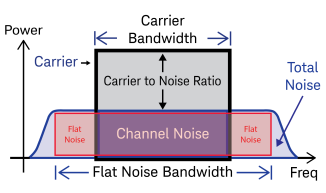
Relationship among each symbol is as follows.


Noise Power Ratio means the ratio of Channel Noise Power to Total Noise Power.
For M9484C: The equation above means that the Total Noise Power becomes larger than Channel Noise Power by dB if Flat Noise Bandwidth and Carrier Bandwidth are the same.
Adds real-time AWGN to the carrier modulated by the waveform being played.
|
GUI Location |
Adjustments > AWGN > AWGN On |
|
SCPI Command |
[:SOURce]:IQOut<channel>:AWGN[:STATe] ON|OFF|1|0 [:SOURce]:IQOut<channel>:AWGN[:STATe]? |
|
SCPI Example |
IQO:AWGN ON IQO:AWGN? |
|
Preset |
OFF |
|
Dependencies |
Option 403 is required to turn on this parameter. |
|
State Saved |
Yes |
|
Initial S/W Revision |
A.01.00 |
|
GUI Location |
Adjustments > AWGN > Carrier to Noise Ratio Format |
|
SCPI Command |
[:SOURce]:IQOut<channel>:AWGN:CNFormat CN|EBNO [:SOURce]:IQOut<channel>:AWGN:CNFormat? |
|
SCPI Example |
IQO:AWGN:CNF EBNO IQO:AWGN:CNF? |
|
Preset |
CN |
|
Choices |
C/N | Eb/No |
|
State Saved |
Yes |
|
Initial S/W Revision |
A.03.00 |
Sets the carrier to noise ratio (C/N) in dB. The carrier power is defined as the total modulated signal power without noise power added. The noise power is applied over the specified bandwidth of the carrier signal.
|
GUI Location |
Adjustments > AWGN > Carrier to Noise Ration > C/N |
|
SCPI Command |
[:SOURce]:IQOut<channel>:AWGN:CN <rel_ampl> [:SOURce]:IQOut<channel>:AWGN:CN? |
|
SCPI Example |
IQO:AWGN:CN 10 dB IQO:AWGN:CN? |
|
Preset |
0 dB |
|
State Saved |
Yes |
|
Min |
Carrier to Noise Ratio may be clipped by the min value of Power
This calculated value is applicable only when both AWGN Status and vector modulation are on. |
|
Max |
This calculated value is applicable only when both AWGN Status and vector modulation are on. |
|
Resolution |
0.01 dB |
|
Step Increment |
0.01 dB |
|
Initial S/W Revision |
A.03.00 |
If signal power is in watts and bit rate is in bits per second, Eb is in units of joules (watt-seconds). N0 is the noise spectral density, the noise power in a 1 Hz bandwidth, measured in watts per hertz or joules.
This function is only available when Carrier to Noise Ratio Format is set to Eb/No.
|
GUI Location |
Adjustments > AWGN > Carrier to Noise Ratio Format set to Eb/No > Eb/No |
|
SCPI Command |
[:SOURce]:IQOut<channel>:AWGN:EBNO <rel_ampl> [:SOURce]:IQOut<channel>:AWGN:EBNO? |
|
SCPI Example |
IQO:AWGN:EBNO 10 dB IQO:AWGN:EBNO? |
|
Preset |
0 dB |
|
State Saved |
Yes |
|
Min |
(Minimum value of C/N) - 10log10(bitRate/carrierBandWidth) |
|
Max |
(Maximum value of C/N) - 10log10(bitRate/carrierBandWidth) |
|
Resolution |
0.01 dB |
|
Step Increment |
0.01 dB |
|
Initial S/W Revision |
A.03.00 |
Sets a value of the carrier bit rate (gross bit rate) for purposes of calculating the Eb/N0 (energy per bit over noise power density at the receiver). When the carrier to noise ratio format is set to Eb/N0, the adjustment of the carrier bit rate will have an immediate impact on the carrier to noise ratio as specified by Eb/N0. The carrier bit rate is derived from the symbol rate and bits per symbol of the modulation.
This function is only available when Carrier to Noise Ratio Format is set to Eb/No.
|
GUI Location |
Adjustments > AWGN > Carrier to Noise Ratio Format set to Eb/No > Carrier Bit Rate (bps) |
|
SCPI Command |
[:SOURce]:IQOut<channel>:AWGN:CBRate [:SOURce]:IQOut<channel>:AWGN:CBRate? |
|
SCPI Example |
IQO:AWGN:CBR 5 IQO:AWGN:CBR? |
|
Preset |
1 bps |
|
State Saved |
Yes |
|
Min |
1 bps |
|
Max |
999 Gbps |
|
Resolution |
0.001 bps |
|
Step Increment |
0.001 bps |
|
Initial S/W Revision |
A.03.00 |
Sets the carrier bandwidth over which the AWGN is applied. The carrier RMS power and the noise power will be integrated over the selected carrier-bandwidth for the purposes of calculating carrier to noise ratio (C/N).
|
GUI Location |
Adjustments > AWGN > Carrier Bandwidth |
|
SCPI Command |
[:SOURce]:IQOut<channel>:AWGN:CBWidth <freq> [:SOURce]:IQOut<channel>:AWGN:CBWidth? |
|
SCPI Example |
IQO:AWGN:CBW 10 Hz IQO:AWGN:CBW? |
|
Preset |
1 Hz |
|
State Saved |
Yes |
|
Min |
1 Hz |
| Max | For Bandwidth, see Vector Modulation Bandwidth Limitations table. |
|
Resolution |
0.001 Hz |
|
Step Increment |
5 kHz |
|
Initial S/W Revision |
A.03.00 |
|
Modified S/W Revision |
A.09.00 |
|
History |
Added M9484Cat A.09.00 |
Selects the flat noise bandwidth value of the real–time noise for an ARB waveform. Typically, this value is set slightly wider than the signal bandwidth.
|
GUI Location |
Adjustments > AWGN > Flat Noise Bandwidth |
|
SCPI Command |
[:SOURce]:IQOut<channel>:AWGN:BANDwidth|BWIDth <freq> [:SOURce]:IQOut<channel>:AWGN:BANDwidth|BWIDth? |
|
SCPI Example |
IQO:AWGN:BAND 10 Hz IQO:AWGN:BAND? |
|
Preset |
For M9484C: 1.6 Hz |
|
State Saved |
Yes |
|
Min |
For M9484C: 1.6 Hz |
| Max | For Bandwidth, see Vector Modulation Bandwidth Limitations table. |
|
Resolution |
For M9484C: 0.8 Hz |
|
Step Increment |
5 kHz |
|
Initial S/W Revision |
A.03.00 |
|
Modified S/W Revision |
A.09.00 |
|
History |
Added M9484C at A.09.00 |
The Power Control Mode can be set to either Total, Carrier, Total Noise, or Channel Noise. Each mode is defined as follows:
|
Total |
Adjusts the total power and C/N (Carrier to Noise Ratio). The carrier power, channel noise power, and total noise power are set by the total power, C/N, and the rest of the noise settings, and change as any noise parameter is adjusted to keep the total power and the C/N at their last specified values. |
|
Carrier |
Adjusts the carrier power and C/N. The total power, channel noise power, and total noise power are set by the carrier power, C/N, and the rest of the noise setting and change as any noise parameter is adjusted to keep the carrier power and the C/N at their last specified values. It can be set manually using the Carrier Power option. |
|
Total Noise |
Adjusts the total noise power and C/N. The total power, channel noise power, and carrier power are set by the total noise power, C/N, and the rest of the noise settings and change as any noise parameter is adjusted to keep the total noise power and the C/N at their last specified values. It can be set manually using the Total Noise Power option. |
|
Channel Noise |
Adjusts the channel noise power and C/N. The total power, total noise power, and carrier power are set by the channel noise power, C/N, and the rest of the noise settings and change as any noise parameter is adjusted to keep the channel noise power and the C/N at their last specified values. It can be set manually using the Noise Power in Channel option. |
|
Flat Noise |
Adjusts the flat noise power and C/N. The total power, channel noise power, and carrier power are set by the flat noise power, C/N, and the rest of the noise settings and change as any noise parameter are adjusted to keep the total noise power and the C/N at their last specified values. It can be set manually using the Flat Noise Power option. |
|
GUI Location |
Adjustments > AWGN > Power Control Mode |
|
SCPI Command |
[:SOURce]:IQOut<channel>:AWGN:POWer:CONTrol[:MODE] TOTal|CARRier|NOISe|NCHannel|NFLat [:SOURce]:IQOut<channel>:AWGN:POWer:CONTrol[:MODE]? |
|
SCPI Example |
IQO:AWGN:POW:CONT NOIS IQO:AWGN:POW:CONT? |
|
Preset |
TOTal |
|
Choices |
Total | Carrier | Total Noise | Channel Noise l Flat Noise |
|
State Saved |
Yes |
|
Initial S/W Revision |
A.03.00 |
|
Modified S/W Revision |
A.12.00 - Added Flat Noise |
GUI function only, no SCPI equivalent commend.
Shows the sum of Total Noise Power and Carrier Power.
|
GUI Location |
Adjustments > AWGN > Total Power |
|
Initial S/W Revision |
A.01.00 |
Sets the current carrier power level.
In Carrier control mode, the total power will be adjusted to achieve the specified carrier power, and the carrier power level will be maintained regardless of changes to the other noise parameters. A change to the total power will change the carrier power setting appropriately to maintain the C/N ratio.
In the other control modes, this will adjust the total power once for the specified carrier power level, after which the carrier power could change if any noise parameters are adjusted.
|
GUI Location |
Adjustments > AWGN > Carrier Power |
|
SCPI Command |
[:SOURce]:IQOut<channel>:AWGN:POWer:CARRier <ampl> [:SOURce]:IQOut<channel>:AWGN:POWer:CARRier? |
|
SCPI Example |
IQO:AWGN:POW:CARR 20 dBm IQO:AWGN:POW:CARR? |
|
Preset |
For M9484C: -104.77 dBm |
|
State Saved |
Yes |
|
Min |
The min value of the carrier power is calculated using the min limit of the total power and C/N.
This calculated value is applicable only when both AWGN Status and vector modulation are on. |
|
Max |
The max value of the carrier power is calculated using the max limit of the total power and C/N.
This calculated value is applicable only when both AWGN Status and vector modulation are on. |
|
Resolution |
0.01 dBm |
|
Step Increment |
5 dBm |
|
Initial S/W Revision |
A.03.00 |
Sets the current channel noise power level.
In the Channel Noise control mode, the total power will be adjusted to achieve the specified channel noise power and the channel noise power level will be maintained regardless of changes to the other noise parameters. A change to the total power will change the channel noise power setting appropriately to maintain the C/N ratio.
In the other control modes, this will adjust the total power once for the specified channel noise power level, after which the channel noise power could change if any noise parameters are adjusted.
|
GUI Location |
Adjustments > AWGN > Channel Noise Power |
|
SCPI Command |
[:SOURce]:IQOut<channel>:AWGN:POWer:NOISe:CHANnel <ampl> [:SOURce]:IQOut<channel>:AWGN:POWer:NOISe:CHANnel? |
|
SCPI Example |
IQO:AWGN:POW:NOIS:CHAN -30 dBm IQO:AWGN:POW:NOIS:CHAN? |
|
Preset |
-123.52 dBm |
|
State Saved |
Yes |
|
Min |
The min value of the channel noise power is calculated using the min limit of the total power and C/N.
This calculated value is applicable only when both AWGN Status and vector modulation are on. |
|
Max |
The max value of the channel noise power is calculated using the max limit of the total power and C/N.
This calculated value is applicable only when both AWGN Status and vector modulation are on. |
|
Resolution |
0.01 dBm |
|
Step Increment |
5 dBm |
|
Initial S/W Revision |
A.03.00 |
Sets the current noise power level for the region of the Flat Noise Bandwidth.
In the Channel Noise control mode, the total power will be adjusted to achieve the specified channel noise power and the flat noise power level will be maintained regardless of changes to the other noise parameters. A change to the total power will change the flat noise power setting appropriately to maintain the C/N ratio.
In the other control modes, this will adjust the total power once for the specified flat noise power level, after which the flat noise power could change if any noise parameters are adjusted.
|
GUI Location |
Adjustments > AWGN > Flat Noise Power |
|
SCPI Command |
[:SOURce]:IQOut<channel>:AWGN:POWer:NOISe:FLAT <ampl> [:SOURce]:IQOut<channel>:AWGN:POWer:NOISe:FLAT? |
|
SCPI Example |
IQO:AWGN:POW:NOIS:FLAT -100 dBm IQO:AWGN:POW:NOIS:FLAT? |
|
Preset |
|
|
State Saved |
Yes |
|
Min |
You can model the minimum of flat noise power as a function of the channel noise power minimum, which itself is calculated using the min limit of total power and C/N.
This calculated value is applicable only when both AWGN Status and Enable Vector Modulation Signal are on. |
|
Max |
You can model the maximum of flat noise power as a function of the channel noise power maximum, which itself is calculated using the min limit of total power and C/N.
This calculated value is applicable only when both AWGN Status and Enable Vector Modulation Signal are on. |
|
Resolution |
0.00000001 dBm |
|
Step Increment |
5 dBm |
|
Initial S/W Revision |
A.11.00 |
Sets the current total noise power level.
In the Noise control mode, the total power will be adjusted to achieve the specified total noise power and the total noise power level will be maintained regardless of changes to the other noise parameters. A change to the total power will change the total noise power setting appropriately to maintain the C/N ratio.
In the other control modes, this will adjust the total power once for the specified total noise power level, after which the total noise power could change if any noise parameters are adjusted.
|
GUI Location |
Adjustments > AWGN > Total Noise Power |
|
SCPI Command |
[:SOURce]:IQOut<channel>:AWGN:POWer:NOISe:TOTal <ampl> [:SOURce]:IQOut<channel>:AWGN:POWer:NOISe:TOTal? |
|
SCPI Example |
IQO:AWGN:POW:NOIS:TOT 15 dBm IQO:AWGN:POW:NOIS:TOT? |
|
Preset |
-122.55 dBm |
|
State Saved |
Yes |
|
Min |
The min value of the total noise power noise power is calculated using the min limit of the total power and C/N.
This calculated value is applicable only when both AWGN Status and vector modulation are on. |
|
Max |
The max value of the total noise power noise power is calculated using the max limit of the total power and C/N.
This calculated value is applicable only when both AWGN Status and vector modulation are on. |
|
Resolution |
0.01 dBm |
|
Step Increment |
5 dBm |
|
Initial S/W Revision |
A.03.00 |
Enables diagnostic control of additive noise, such that only the noise, only the carrier, or the sum of both the noise and the carrier are output from the internal baseband generator. With ALC off, this feature enables direct measurement of just the carrier or the noise contributions to the total power. The system will still behave as if both the noise and the carrier are present on the output when it comes to determining the Auto Modulation Attenuation and the RMS level for RMS Power Search.
|
GUI Location |
Adjustments > AWGN > Output Mux Mode |
|
SCPI Command |
[:SOURce]:IQOut<channel>:AWGN:MUX SUM|CARRier|NOISe [:SOURce]:IQOut<channel>:AWGN:MUX? |
|
SCPI Example |
IQO:AWGN:MUX SUM IQO:AWGN:MUX? |
|
Preset |
SUM |
|
Choices |
Carrier+Noise | Carrier | Noise |
|
State Saved |
Yes |
|
Initial S/W Revision |
A.03.00 |
Adds a CW tone placed relative to the carrier modulated by the waveform being played.
In some cases, better RF performance of a CW interferer is required, or you may need a dynamic range that is greater than the dynamic range available. For these cases, additional RF outputs can be used to generate the CW interferer, combining the waveforms in RF external to the instrument, to minimize the intermodulation products and improve EVM performance.
Enables or disables adding a CW tone (an interferer) to the carrier modulated by the waveform being played.
Enables or disables adding a CW tone (an interferer) to the carrier modulated by the waveform being played. The CW tone cannot be on at the same time as AWGN in the Adjustment block or Frequency Offset in the Signal block; setting CW Interferer on will turn off AWGN and set baseband frequency offset to 0 Hz.
With M9484C Option 8SG, only up to 7 signals are available when CW Interferer is on. If Signal 8 was enabled when CW Interferer is set to on, Signal 8 will be disabled.
|
GUI Location |
Adjustments > CW Interferer > CW Interferer On |
|
SCPI Command |
[:SOURce]:IQOut<channel>:CWINterferer[:STATe] ON|OFF|1|0 [:SOURce]:IQOut<channel>:CWINterferer[:STATe]? |
|
SCPI Example |
IQO:CWIN ON IQO:CWIN? |
|
Preset |
OFF |
|
Dependencies |
Option 403 is required to turn on this setting. |
|
Couplings |
For M9484C with Option 8SG: If Signal 8 is enabled when CW Interferer is on, it will be disabled and a Settings Conflict error message is generated |
|
State Saved |
Yes |
|
Initial S/W Revision |
A.08.00 |
Sets the offset of the CW interferer from the CW carrier, which is the center of the modulated waveform.
|
GUI Location |
Adjustments > CW Interferer > Frequency Offset |
|
SCPI Command |
[:SOURce]:IQOut<channel>:CWINterferer:FREQuency:OFFSet <frequency> [:SOURce]:IQOut<channel>:CWINterferer:FREQuency:OFFSet? |
|
SCPI Example |
IQO:CWIN:FREQ:OFFS -10 MHZ IQO:CWIN:FREQ:OFFS? |
|
Preset |
0 Hz |
|
State Saved |
Yes |
| Min |
- (BW/2) For BW, see Vector Modulation Bandwidth Limitations table. |
| Max |
BW/2 For BW, see Vector Modulation Bandwidth Limitations table. |
|
Resolution |
M9484C: 0.00001 Hz |
|
Step Increment |
5 kHz |
|
Initial S/W Revision |
A.08.00 |
Sets the power level at the input of the CW interferer: the signal block power + AWGN.
When CW Interferer is on, a coupling exists between the Signal power and the RF Output Power Total (in the RF Output block); as the Signal power is changed the RF Output Power Total is adjusted to reflect Signal power + CW Interferer power. If the RF Output Power Total is changed, the Signal power is adjusted to reflect RF Output Power Total – CW Interferer power. If the range of Signal power is exhausted, and the CW Interferer mode is Absolute, the Absolute power is then adjusted.
|
GUI Location |
Adjustments > CW Interferer > Signal Power |
|
SCPI Command |
[:SOURce]:IQOut<channel>:CWINterferer:POWer:SIGNal <ampl> [:SOURce]:IQOut<channel>:CWINterferer:POWer:SIGNal? |
|
SCPI Example |
IQO:CWIN:POW:SIGN 20 dBm IQO:CWIN:POW:SIGN? |
|
Preset |
-103.52 dBm |
|
State Saved |
Yes |
|
Min |
The min value of the signal power is calculated using the min limit of the total power and CW Interferer Power. This calculated value is applicable only when both CW Interferer State and vector modulation are on. |
|
Max |
The max value of the signal power is calculated using the max limit of the RF Output Power Total and CW Interferer Power. See Max value of RF Output Power Total This calculated value is applicable only when both CW Interferer State and vector modulation are on. |
|
Resolution |
0.01 dBm |
|
Step Increment |
5 dBm |
|
Initial S/W Revision |
A.03.00 |
The CW interferer power can be specified as either relative to the signal power, or an absolute power level.
|
GUI Location |
Adjustments > CW Interferer > CW Interferer Power > Control Mode |
|
SCPI Command |
[:SOURce]:IQOut<channel>:CWINterferer:POWer:MODE RELative|ABSolute [:SOURce]:IQOut<channel>:CWINterferer:POWer:MODE? |
|
SCPI Example |
IQO:CWIN:POW:MODE REL IQO:CWIN:POW:MODE? |
|
Preset |
ABS |
|
Range |
RELative | ABSolute |
|
State Saved |
Yes |
|
Initial S/W Revision |
A.08.00 |
Controls the relative power of the CW Interferer with respect to the modulated waveform, when the CW Interferer mode is Relative. Note that as CW Interferer power increases, all other signals will lose fidelity. For measurements that need both high dynamic range and high-fidelity low power signals, an instrument with a second RF Channel is recommended.
|
GUI Location |
Adjustments > CW Interferer > CW Interferer Power > Control Mode (Relative) > Relative to Signal Power |
|
SCPI Command |
[:SOURce]:IQOut<channel>:CWINterferer:POWer:RELative <ampl> [:SOURce]:IQOut<channel>:CWINterferer:POWer:RELative? |
|
SCPI Example |
IQO:CWIN:POW:REL -1 IQO:CWIN:POW:REL? |
|
Preset |
0 dB |
|
State Saved |
Yes |
|
Min |
-96 dB |
|
Max |
96 dB |
|
Resolution |
0.01 dB |
|
Step Increment |
5 dB |
|
Initial S/W Revision |
A.08.00 |
Controls the absolute power of the CW Interferer, when the CW Interferer mode is Absolute. Note that as the CW Interferer power increases, all other signals will lose fidelity. For measurements that need both high dynamic range and high-fidelity low power signals, an instrument with a second RF Channel is recommended.
When CW Interferer is on, a coupling exists between the RF Output Power Total (in the RF Output block) and the CW Interferer absolute power; if the RF Output Power Total is adjusted lower in amplitude such that Signal Power runs out of range, the level of the absolute power is reduced and a clipping message is displayed.
|
GUI Location |
Adjustments > CW Interferer > CW Interferer Power > Control Mode (Absolute) > Absolute |
|
SCPI Command |
[:SOURce]:IQOut<channel>:CWINterferer:POWer:ABSolute <ampl> [:SOURce]:IQOut<channel>:CWINterferer:POWer:ABSolute? |
|
SCPI Example |
IQO:CWIN:POW:ABS -1 IQO:CWIN:POW:ABS? |
|
Preset |
-96 dBm |
|
State Saved |
Yes |
|
Min |
-120 dBm |
|
Max |
23 dBm (limited by max power options; cannot be higher than settable power) See max value of Power (Total RMS). |
|
Resolution |
0.01 dB |
|
Step Increment |
5 dB |
|
Initial S/W Revision |
A.08.00 |
Displays the sum of CW interferer power (assumed to be on), AWGN power (if on), and the signal block's power.
No SCPI command available for this feature.