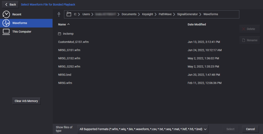
The ![]() Signal block sets up the instrument’s vector modulation. This includes enabling vector modulation, selecting a waveform file for playback, or selecting optional signal modes, such as Multitone. See also, Vector Modulation Bandwidth Limitations.
Signal block sets up the instrument’s vector modulation. This includes enabling vector modulation, selecting a waveform file for playback, or selecting optional signal modes, such as Multitone. See also, Vector Modulation Bandwidth Limitations.
Unless specified as "Bonded," this topic primarily describes capabilities for use when the Configuration is Independent, 2 Tx Coherent, or MIMO. For bonded configurations, do not use SCPI commands described in this topic unless they are specified as "Bonded."
For bonded configurations, be sure to use bonding-supported SCPI commands only. Using unsupported SCPI commands in a bonded configuration will impair the fidelity of the waveform. In these cases, the unsupported SCPI commands are still accepted, but no error or warning is generated.
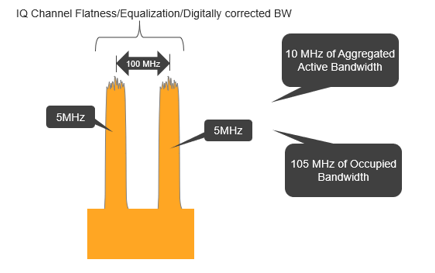
The vector modulation bandwidth is based on the instrument’s optional capabilities and operating settings. The bandwidth is as follows:
Table: M9484C Vector Modulation BW
|
Operating Settings |
Bandwidth Options |
|||||||
|---|---|---|---|---|---|---|---|---|
|
R25 |
R2E |
R10 |
R1E |
B5X |
B2X |
B1X |
||
|
Max Sample Rate (MHz) |
3000 |
3000 |
1228.8 |
1228.8 |
600 |
300 |
200 |
|
|
Max Bandwidth (MHz) |
2500 |
2500 |
1024 |
1024 |
500 |
250 |
160* |
|
|
Modulation Bandwidth (MHz) |
9 kHz ≤ f ≤ 5.75 GHz |
2500 |
2500 |
1024 |
1024 |
500 |
250 |
160 |
|
5.75 GHz < f ≤ 31.25 GHz |
2500 |
2200 |
1024 |
1024 |
500 |
250 |
160 |
|
|
31.25 GHz < f ≤ 31.838 GHz |
2500 |
1024 |
1024 |
1024 |
500 |
250 |
160 |
|
|
31.838 GHz < f < 36.962 GHz |
2500 |
550 |
1024 |
550 |
500 |
250 |
160 |
|
|
36.962 GHz ≤ f < 37.55 GHz |
2500 |
1024 |
1024 |
1024 |
500 |
250 |
160 |
|
|
37.55 GHz ≤ f < 89.05 GHz |
2500 |
2200 |
1024 |
1024 |
500 |
250 |
160 |
|
|
89.05 GHz ≤ f |
2500 |
2500 |
1024 |
1024 |
500 |
250 |
160 |
|
* Actually 166.66666
If your configuration exceeds the available bandwidth, the following message appears in the Notifications Area:
Modulation BW is greater than instrument’s BW (<bandwidth>) at this frequency
In this scenario, you may operate the instrument with the resulting performance, or reduce the modulation setting to resume operation within the available bandwidth, as determined by the Mode in use.
Turns vector modulation signal on and off.
When I/Q Modulation Source is Internal, toggling this setting also toggles I/Q Modulation On to the same state.
|
GUI Location |
Signals > General tab > Enable |
|
SCPI Command |
[:SOURce]:GROup<group>:SIGNal<signal>[:STATe] ON|OFF|1|0 [:SOURce]:GROup<group>:SIGNal<signal>[:STATe]? |
|
SCPI Example |
GRO:SIGN ON GRO:SIGN? |
|
Notes |
If using floating licenses, be sure to query "SYST:ERR?" after attempting to set "SIGN ON"; if the license was not obtained from the server the error -310,"System error; feature not licensed" is returned. |
|
Preset |
OFF |
|
Coupling |
When Enable Vector Modulation is set to On, if I/Q Output Amplitude Control is ON, no coupling occurs; meaning the current state of Output Modulation I/Q is unchanged and Output Modulation I/Q Source is unchanged. When Enable Vector Modulation is set to On, if I/Q Output Amplitude Control is OFF, if Output Modulation I/Q Modulation Source is Internal the I/Q Modulation state is set to ON. When the Loaded Application is empty or the Signal's Application doesn't match the Loaded Application, Enable Vector Modulation Signal is set to OFF and is not changeable. |
|
State Saved |
No
|
|
Dependencies |
For instruments with Option 8SG:
|
|
Backwards Compatibility SCPI |
The following commands are not recommended. They are for the convenience of users with existing remote programs developed for earlier versions of the signal generator or ported from a similar product. [:SOURce]:RADio[1]:ARB[:STATe] Alias [:SOURce]:SIGNal[1][:STATe] to :SOURce:GROup1:SIGNal1[:STATe] Alias [:SOURce]:SIGNal2[:STATe] to :SOURce:GROup2:SIGNal1[:STATe] N51xxB: :RADio:MTONe:ARB[:STATe] |
| Backwards Compatibility Notes |
For N51xxB: For M9484C with N7621APPC: Alias :RADio:MTONe:ARB[:STATe] ON to :SOURce:GROup1:SIGNal1:MODE MTON; :SOURce:GROup1:SIGNal1[:STATe] ON Alias :RADio:MTONe:ARB[:STATe] OFF to :SOURce:GROup1:SIGNal1[:STATe] OFF |
|
Initial S/W Revision |
A.01.00 |
|
Modified S/W Revisions |
A.09.00 Added :GROup keyword, M9484APPC or M9484AP1C A.10.00 Updated the behavior for the real-time mode A.16.20 Changed State Saved from Yes to No A.18.00 Added MTONE State Command to Backwards Compatibility |
Turns vector modulation signal on and off. The control is grayed-out until a .bnd file has been selected, either manually or as the result of a successful bonded calibration.
|
GUI Location |
System Menu > Configure Channels > Bonded > Signals > Enable |
|
SCPI Command |
[:SOURce]:GROup<group>:CBONded[:STATe] ON|OFF|1|0 [:SOURce]:GROup<group>:CBONded[:STATe]? |
|
SCPI Example |
GRO:CBON ON GRO:CBON? |
|
Couplings |
Cannot be turned ON if the Bonded Waveform File is not a .bnd file. If Enabled is ON and the Bonded Waveform File is set to a file that is not a .bnd, Enabled is set to OFF. |
|
Preset |
OFF |
|
State Saved |
Yes |
|
Range |
OFF | ON |
|
SCPI Change |
[:SOURce]:CBONded<bondingset>[:STATe] ON|OFF|1|0 has been changed to [:SOURce]:GROup<group>:CBONded[:STATe] ON|OFF|1|0. Prior use of :SOUR:CBON or :SOUR:CBON1 is now :SOUR:GRO1:CBON. |
|
Initial S/W Revision |
A.07.00 |
|
Modified S/W Revision |
A.10.00 Changed SCPI: Added :GROup<group> and removed <bondingset> from :CBONded |
Selects the vector modulation signal mode. Some signal modes are optional capabilities and require a license to enable.
When using floating licenses with automatic check out, all available signal modes are displayed in the GUI. The license is checked out from the server when the signal mode is selected. The license is checked in (returned to the server) when preset is performed.
|
Capability |
SCPI Syntax |
License |
|---|---|---|
|
AMOD |
N7642APPC |
|
|
MTON |
N7621APPC |
|
|
SSB |
N7621APPC |
|
|
WAV |
NA |
|
|
AWGN |
Option 403 |
|
|
RTIM |
One of the following licenses:
|
|
|
ODIStreaming |
M9484C-DS1 |
|
| Envelope Tracking |
ENVelope |
For single-channel configuration:
For multi-channel configuration:
|
|
GUI Location |
Signals > General tab > Mode |
|
SCPI Command |
[:SOURce]:GROup<group>:SIGNal<signal>:MODE AMODulation|MTONe|SSB|WAVeform|AWGN|RTIMe|ODIStreaming|ENVelope [:SOURce]:GROup<group>:SIGNal<signal>:MODE? |
|
SCPI Example |
GRO:SIGN:MODE AMOD GRO:SIGN:MODE? |
|
Dependencies |
AWGN:
For M9484C: ODI Streaming
For M9484C: Envelope Tracking
|
|
Preset |
WAVeform |
|
Notes |
For M9484C, the following licenses are required. MTONe and SSB: N7621APPC AMOD: N7642APPC RTIMe: N7631APPC, N7624APPC, N7625APPC, N7609APPC, or N7602AP1C When floating licenses are used, licenses are returned to the server when a preset is performed. Beginning with version A.09.00 5G NR and Custom Modulation have been moved from Signal Modes to Applications. See 5G NR Help. The command [:SOURce]:RADio:SELect NR5G is used to load the 5G NR Application SCPI. |
|
State Saved |
Yes |
|
Choices |
Analog Modulation | Multitone | Single Tone | Waveform File | AWGN | Real-Time | ODI Streaming|Envelope Tracking |
|
Backwards Compatibility SCPI |
The following commands are not recommended. They are for the convenience of users with existing remote programs developed for earlier versions of the signal generator or ported from a similar product. Alias [:SOURce]:SIGNal[1]:MODE to :SOURce:GROup1:SIGNal1:MODE Alias [:SOURce]:SIGNal2:MODE to :SOURce:GROup2:SIGNal1:MODE |
|
Initial S/W Revision |
A.01.00 |
|
Modified S/W Revision |
A.03.00 Added AWGN A.06.00 Changed Single Side-band to Single Tone, and added CMODulation A.09.00 Added :GROup keyword. Removed CMODulation and NR5G A.10.00 Added RTIMe A.11.50 Updated for M9484C A.16.00 Added ODI Streaming for M9484C A.19.01 Added Envelope Tracking for M9484C |
Option PCH only.
Provided to allow programmatic compatibility with other Keysight Technologies signal generators.
Sync Off – The channels are not synchronized. Each signal plays based on its trigger settings.
|
GUI Location |
Signals > Synchronization Role |
|
SCPI Command |
[:SOURce]:GROup<group>:SIGNal<signal>:SROLe OFF [:SOURce]:GROup<group>:SIGNal<signal>:SROLe? |
|
SCPI Example |
GRO:SIGN:SROL SEC GRO:SIGN:SROL? |
|
Notes |
Without Option PCH: Attempting to set SROLe raises error -221, Settings Conflict; Option PCH is required. With Option PCH: Synchronization Role is Off and not changeable. Sending the SCPI command raises error 703, Feature not supported; on {Model#}, see Global Trigger. |
|
Choices |
Sync Off | Primary | Secondary |
|
Preset |
Sync Off |
|
Dependencies |
Available only with Option PCH and Configuration is set to Independent. |
|
State Saved |
Yes |
|
Backwards Compatibility SCPI |
The following commands are not recommended. They are for the convenience of users with existing remote programs developed for earlier versions of the signal generator or ported from a similar product. Alias [:SOURce]:SIGNal[1]:SROLe to :SOURce:GROup1:SIGNal1:SROLe Alias [:SOURce]:SIGNal2:SROLe to :SOURce:GROup2:SIGNal1:SROLe |
|
Initial S/W Revision |
A.01.00 |
|
Modified S/W Revision |
A.06.00 A.09.00 Added :GROup keyword A.12.00 Generated error for M9484C |
Allows scaling the signal down without disrupting the output. The dynamic range is not adjusted (optimized) when this value is adjusted. This signal’s power relationship with other signals, including noise, is not adjusted when this value is changed. When the signal’s power is adjusted using other features, then this value is reset to 0 dB.
|
GUI Location |
Signals > General tab > Signal Attenuation |
|
SCPI Command |
[:SOURce]:GROup<group>:SIGNal<signal>:POWer:SATTenuation <rel_ampl> [:SOURce]:GROup<group>:SIGNal<signal>:POWer:SATTenuation? |
|
SCPI Example |
GRO:SIGN:POW:SATT -3 GRO:SIGN:POW:SATT? |
|
Dependencies |
When Mode is AWGN, this setting is disabled. |
|
Preset |
0 dB |
|
State Saved |
Yes |
|
Min |
For M9484C: -100 dB |
|
Max |
0 dB |
|
Resolution |
0.01dB |
|
Backwards Compatibility SCPI |
The following commands are not recommended. They are for the convenience of users with existing remote programs developed for earlier versions of the signal generator or ported from a similar product. Alias [:SOURce]:SIGNal[1]:POWer:SATTenuation to :SOURce:GROup1:SIGNal1:POWer:SATTenuation Alias [:SOURce]:SIGNal2:POWer:SATTenuation to :SOURce:GROup2:SIGNal1:POWer:SATTenuation |
|
Initial S/W Revision |
A.01.00 |
|
Modified S/W Revision |
A.04.00: Changed the title/label from Baseband Power to Signal Attenuation and moved its location out of the Waveform Playback Setup area. A.09.00: Added :GROup keyword. A.10.00: Changed minimum value for M9484C. |
Available with M9484C Option 8SG. This feature disables or enables the I/Q component of a signal without adjusting any power relationships between any signals, including noise. The channel will behave as if the signal is not muted, but the signal will not contribute any power to the outputs of the channel. Turning the signal off and on with this feature means that there is no other disruption to the outputs besides this signal having no power or the requested power. For instance, triggering of the signal is not disabled when muting occurs. Markers also continue to be output. This feature is independent of the Signal Attenuation feature.
|
GUI Location |
Signals > General tab > Mute |
|
SCPI Command |
[:SOURce]:GROup<group>:SIGNal<signal>:POWer:MUTE[:STATe] ON|OFF|1|0 [:SOURce]:GROup<group>:SIGNal<signal>:POWer:MUTE[:STATe]? |
|
SCPI Example |
GRO:SIGN:POW:MUTE 1 GRO:SIGN:POW:MUTE? |
|
Notes |
On instruments without Option 8SG, sending the SCPI command does not generate an error |
|
Preset |
OFF |
|
State Saved |
Yes |
|
Initial S/W Revision |
A.09.00 |
The sample rate used by the signal is
|
GUI Location |
Signals > Signal Summary (select signal) > General (default) > Sample Rate |
|
SCPI Command |
[:SOURce]:GROup<group>:SIGNal<signal>:SCLock:RATE? |
|
SCPI Example |
GRO:SIGN:SCL:RATE? |
|
State Saved |
No |
|
Min |
0 Hz |
| Max |
For Sample Rate, see Vector Modulation Bandwidth Limitations table. For M9484C: When Fading is On, the maximum sample rate is 2.4 GHz. |
|
Initial S/W Revision |
A.10.00 |
Click this button to access the Analysis screen which provides the complementary cumulative distribution function (CCDF) measurement for a given signal or file.
The CCDF measurement is a statistical power measurement that indicates the probability of a signal power reaching or exceeding a given power value. CCDF represents the complement of the cumulative distribution function (CDF) that is, CCDF = 1 – CDF.
|
GUI Location |
Signals > General tab > Analysis |
Each measurement can be defined as follows:
CDF = Probability(x < K)
CCDF = Probability(x ≥ K)
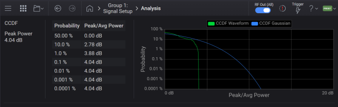
The Signal Generator application visualizes the CCDF curve with probability (%) on the y-axis and power (dB) on the x-axis. Power on the x-axis is relative to the average signal power, so 0 dB is the average power of the signal. As an example, a value of 2 dB and 12% on the curve indicates that there is a 12% probability that the signal power will reach 2 dB or more above the average power.
Behind the CCDF curve, another line is drawn to represent the Gaussian noise CCDF reference.
|
SCPI Command |
[:SOURce]:GROup<group>:SIGNal<signal>:CCDF:DATA? |
|
SCPI Example |
:GRO:SIGN:CCDF:DATA? |
| Preset | 0,0,0,0,0,0,0,0 |
| State Saved | No |
| Dependencies |
This CCDF calculation has the following requirements:
|
| Notes |
Runs the CCDF calculation then retrieves a list of floating point measurement results. Returns 8 scalar results:
|
|
Initial S/W Revision |
A.17.00 |
|
SCPI Command |
:CALCulate:CCDF:DATA? <waveform file> |
|
SCPI Example |
:CALC:CCDF:DATA? "mywaveform.wfm" |
| Preset | 0,0,0,0,0,0,0,0 |
| State Saved | No |
| Dependencies | See the Dependencies for Calculate CCDF for Signal. |
| Notes | See the Notes for Calculate CCDF for Signal. |
|
Initial S/W Revision |
A.17.00 |
Clears the phase accumulation resulting from a non-zero frequency offset.
When using frequency offset, dynamic range is managed by the instrument to reduce DAC overrange. Phase Accumulator Reset restores the dynamic range when the frequency offset is set to zero.
When the baseband Frequency Offset is non-zero, the hardware rotator accumulates phase shift of the baseband signal. This residual phase remains even after the offset value is returned to zero. While there is a non-zero residual phase present in the signal, the instrument will automatically prevent DAC overrange errors from occurring by scaling the signal down by 1/square root of 2.
|
GUI Location |
Signals > General tab > Reset Phase Accumulator |
|
SCPI Command |
[:SOURce]:GROup<group>:SIGNal<signal>:FREQuency:OFFSet:PHASe:RESet |
|
SCPI Example |
GRO:SIGN:FREQ:OFFS:PHAS:RES |
|
Backwards Compatibility SCPI |
The following commands are not recommended. They are for the convenience of users with existing remote programs developed for earlier versions of the signal generator or ported from a similar product. [:SOURce]:RADio[1]:ARB:BASeband:FREQuency:OFFSet:PHASe:RESet Alias [:SOURce]:SIGNal[1]:FREQuency:OFFSet:PHASe:RESet to :SOURce:GROup1:SIGNal1:FREQuency:OFFSet:PHASe:RESet Alias [:SOURce]:SIGNal2:FREQuency:OFFSet:PHASe:RESet to :SOURce:GROup2:SIGNal1:FREQuency:OFFSet:PHASe:RESet |
|
Notes |
This command clears the phase accumulation and thus zeros the phase shift. For M9484Cwith Option 8SG: This command only performs a reset if the signal’s frequency offset is 0 Hz. If more than one signal is active at the same time and any have a non-zero frequency offset, all of the signals will still be scaled down by 1/square root of 2. |
|
Initial S/W Revision |
A.08.00 |
|
Modified S/W Revision |
A.09.00 Added :GROup keyword |
Sets the frequency offset for the vector modulation on the indicated Signal. The offset is the distance from the channel’s RF center frequency to the center of the modulation bandwidth. If you set frequency offset to a non-zero value, and then return the offset to zero hertz, it is recommended you perform Reset Phase Accumulator.
|
GUI Location |
Signals > General tab > Frequency Offset |
|
SCPI Command |
[:SOURce]:GROup<group>:SIGNal<signal>:FREQuency:OFFSet <frequency> [:SOURce]:GROup<group>:SIGNal<signal>:FREQuency:OFFSet? |
|
SCPI Example |
GRO:SIGN:FREQ:OFFS 25 MHz GRO:SIGN:FREQ:OFFS? |
|
Preset |
0 |
|
Couplings |
If CW Interferer is ON and the Frequency Offset is set to a non-zero value, CW Interferer is set to OFF and a Settings Conflict error message is generated. For M9484C with Option 8SG, when Absolute Frequency Control is set to ON:
|
|
Notes |
Attempting to set Frequency Offset to non-zero Hz while CW interferer is ON raises the error -221, "Settings conflict; Baseband Frequency Offset cannot be used when CW Interferer is ON." |
|
State Saved |
Yes |
| Min |
- (BW/2) For BW, see Vector Modulation Bandwidth Limitations table. |
| Max |
BW/2 For BW, see Vector Modulation Bandwidth Limitations table. |
|
Resolution |
0.00001 Hz |
|
Backwards Compatibility SCPI |
The following commands are not recommended. They are for the convenience of users with existing remote programs developed for earlier versions of the signal generator or ported from a similar product. [:SOURce]:RADio[1]:ARB:BASeband:FREQuency:OFFSet Alias [:SOURce]:SIGNal[1]:FREQuency:OFFSet to :SOURce:GROup1:SIGNal1:FREQuency:OFFSet Alias [:SOURce]:SIGNal2:FREQuency:OFFSet to :SOURce:GROup2:SIGNal1:FREQuency:OFFSet |
|
Initial S/W Revision |
A.08.00 |
|
Modified S/W Revision |
A.09.00 Added :GROup keyword |
Available with Option 8SG.
Applies to M9484C only.
The ∆ phase rotation of the I/Q.
A positive value rotates counterclockwise in the I/Q plane. Phase offset is added to each signal path and applied when the signal starts playing, or when the ∆ Phase is reconfigured. To align ∆ phases over all signals, start signals by using any common hardware/software trigger or global trigger.
|
GUI Location |
Signals > General tab > ∆ Phase |
|
SCPI Command |
[:SOURce]:GROup<group>:SIGNal<signal>:PHASe <angle> [:SOURce]:GROup<group>:SIGNal<signal>:PHASe? |
|
SCPI Example |
GRO:SIGN:PHAS 30 deg GRO:SIGN:PHAS? |
|
Notes |
Unit is degree. The value can also be set in radians. UP/DOWN increment is always 0.01. On instruments without Option 8SG, sending the SCPI command does not generate an error. Wrap the value when it exceeds the limits. |
|
Preset |
0 degrees |
|
State Saved |
Yes |
|
Min |
-360 degrees |
|
Max |
360 degrees |
|
Resolution |
0.001 degrees |
|
Initial S/W Revision |
A.09.00 |
|
Modified at S/W Revision |
A.18.00 - wrap the value when it exceeds the limits |
Available with Option 8SG.
Applies to M9484C only.
Sets the absolute frequency for the vector modulation on the indicated signal.
|
GUI Location |
Signals > General tab > Absolute Frequency |
|
SCPI Command |
[:SOURce]:GROup<group>:SIGNal<signal>:FREQuency:ABSolute <frequency> [:SOURce]:GROup<group>:SIGNal<signal>:FREQuency:ABSolute? |
|
SCPI Example |
GRO:SIGN:FREQ:ABS 7 GHZ GRO:SIGN:FREQ:ABS? |
|
Preset |
1 GHz |
|
State Saved |
Yes |
| Couplings |
When Absolute Frequency Mode is ON:
When Absolute Frequency Mode is OFF:
|
| Notes | A signal’s Absolute Frequency is affected by the RF Channel’s Frequency Offset, Frequency Reference, and Frequency Multiplier. |
|
Min |
9 kHz |
|
Max |
Max Frequency + Max BW / 2 For BW, see Vector Modulation BW Table. For Max Frequency, see Frequency (CW). |
| Unavailable Range |
For M9484C: Unavailable Range Lower Limit + Max BW / 2 < frequency < Unavailable Range Upper Limit - Max BW / 2 For Unavailable Range, see Frequency (CW). For BW, see Vector Modulation BW Table. |
|
Resolution |
0.00001 Hz |
|
Initial S/W Revision |
A.17.00 |
Available with Option 8SG.
Applies to M9484C only.
This power setting is with respect to other signals. For instance, if all signals are -3 dB (or any other single constant), they all have the same power level – that is, the total power divided by the number of signals.
The signals take their part of the total RF output power according to the relative power relationships between signals, which determines their absolute power.
Note that Signal Attenuation and Mute independently scale down or eliminate the signals output respectively at the RF output, but the system's power control entirely ignores this.
|
GUI Location |
Signals > General tab > Relative Power |
|
SCPI Command |
[:SOURce]:GROup<group>:SIGNal<signal>:POWer:RELative <ampl_rel> [:SOURce]:GROup<group>:SIGNal<signal>:POWer:RELative? |
|
SCPI Example |
GRO:SIGN:POW:REL -3 DB GRO:SIGN:POW:REL? |
|
Notes |
On instruments without Option 8SG, sending the SCPI command does not generate an error. |
| Couplings |
For M9484C with Option 8SG:
|
|
Preset |
0 dB |
|
State Saved |
Yes |
|
Min |
-120 dB |
|
Max |
100 dB |
|
Resolution |
0.01 dBm |
|
Initial S/W Revision |
A.09.00 |
Available with Option 8SG.
Applies to M9484C only.
Sets the absolute power for the vector modulation on the indicated signal.
|
GUI Location |
Signals > General tab > Absolute Power |
|
SCPI Command |
[:SOURce]:GROup<group>:SIGNal<signal>:POWer:ABSolute <ampl> [:SOURce]:GROup<group>:SIGNal<signal>:POWer:ABSolute? |
|
SCPI Example |
GRO:SIGN:POW:ABS 3 DBM GRO:SIGN:POW:ABS? |
| Couplings |
When Absolute Power Control is ON:
When Absolute Power Control is OFF, the value is calculated based on Power (Total RMS) and Relative Powers of enabled signals. |
| Notes | A signals’ Absolute Power is affected by the RF Channel Power, Amplitude Reference and Amplitude Offset. |
|
Preset |
-100 dBm |
|
State Saved |
Yes |
|
Min |
minimum Power (Total RMS) |
|
Max |
minimum Power (Total RMS) |
|
Resolution |
0.01 dBm |
|
Initial S/W Revision |
A.17.00 |
For channel bonding configurations, note the following:
The trigger configuration can be adjusted after the bonding process has completed.
Use Signal 1 for SCPI commands when configuring the triggering.
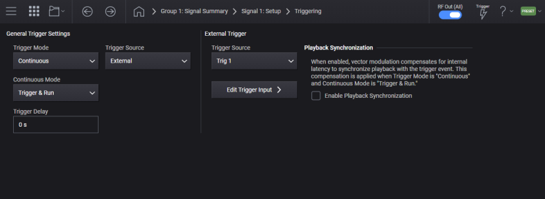
Sets the trigger mode (or type), determining how the waveform plays when triggered. These mode selections are described in the table below.
Triggers control the playback by telling the signal generator when to play the modulating signal (waveform). Depending on the trigger settings, the waveform playback can occur once or continuously.
A trigger signal comprises both positive and negative signal transitions (states), which are also called high and low periods. You can configure the signal generator to trigger on either state of the trigger signal. It is common to have multiple trigger signals, also referred to as trigger occurrences or events, occur when the signal generator requires only a single trigger. In this situation, the signal generator’s action is based on the setting within the trigger mode.
When you select a trigger mode, you may lose the signal (carrier plus modulation) from the RF output until you trigger the waveform. This is because the signal generator sets the I and Q signals to zero volts prior to the first trigger event, which suppresses the carrier. After the first trigger event, the waveform’s final I and Q levels determine whether you will see the carrier signal or not (zero = no carrier, other values = carrier visible). At the end of most files, the final I and Q points are set to a value other than zero.
Continuous: The framed data sequence repeats continuously until you turn the signal off or select a different waveform, or trigger mode. The sequence restarts every time the previous playback is completed.
Single: The framed data sequence plays once for every trigger received.
Segment Advance: For M9484C. The trigger controls the segment advance within a waveform sequence. To use this choice, a waveform sequence must be the active waveform.
|
GUI Location |
Signals >Trigger tab> Trigger Mode |
|
SCPI Command |
[:SOURce]:GROup<group>:SIGNal<signal>:TRIGger:TYPE CONTinuous|SINGle|SADVance [:SOURce]:GROup<group>:SIGNal<signal>:TRIGger:TYPE? |
|
SCPI Example |
GRO:SIGN:TRIG:TYPE SING GRO:SIGN:TRIG:TYPE? |
|
Choices |
Continuous | Single |
|
Notes |
For M9484C, SADVance is available when the Signal Mode is Waveform File, and the selected waveform file is a sequence. Attempting to set SADVance without these requirements raises the error -221, "Settings conflict; SADVance not allowed until waveform sequence is selected". This occurs when the indicated signal is already enabled, or when the signal is transitioned to the enabled state. |
|
Preset |
CONT |
|
State Saved |
Yes |
|
Backwards Compatibility SCPI |
The following commands are not recommended. They are for the convenience of users with existing remote programs developed for earlier versions of the signal generator or ported from a similar product. [:SOURce]:RADio[1]:ARB:TRIGger:TYPE Alias [:SOURce]:SIGNal[1]:CMODulation:TRIGger:TYPE to :SOURce:GROup1:SIGNal1:TRIGger:TYPE Alias [:SOURce]:SIGNal2:CMODulation:TRIGger:TYPE to :SOURce:GROup2:SIGNal1:TRIGger:TYPE Alias [:SOURce]:SIGNal[1]:MTONe:TRIGger:TYPE to :SOURce:GROup1:SIGNal1:TRIGger:TYPE Alias [:SOURce]:SIGNal2:MTONe:TRIGger:TYPE to :SOURce:GROup2:SIGNal1:TRIGger:TYPE Alias [:SOURce]:SIGNal[1]:NR5G:TRIGger:TYPE to :SOURce:GROup1:SIGNal1:TRIGger:TYPE Alias [:SOURce]:SIGNal2:NR5G:TRIGger:TYPE to :SOURce:GROup2:SIGNal1:TRIGger:TYPE Alias [:SOURce]:SIGNal[1]:WAVeform:TRIGger:TYPE to :SOURce:GROup1:SIGNal1:TRIGger:TYPE Alias [:SOURce]:SIGNal2:WAVeform:TRIGger:TYPE to :SOURce:GROup2:SIGNal1:TRIGger:TYPE |
|
Initial S/W Revision |
A.01.00 |
|
Modified S/W Revision |
A.09.00 Added :GROup keyword, moved subsystem up so as not to be specific to Signal Mode A.11.50 Added segment advance for M9484C |
Selects the waveform’s response to a trigger signal while using the continuous trigger mode.
Free Run: The waveform is immediately triggered and played when Enable Vector Modulation Signal is turned on and a valid waveform file is selected. The waveform repeats until you turn off Enable Vector Modulation Signal, select another trigger, or choose another waveform file. Triggers received while the waveform is playing are ignored.
For M9484C. Free Run is not available when Trigger Source is Global Trigger.
Trigger & Run: The waveform waits for a trigger before it starts playing. When the waveform receives the trigger, it plays continuously until you turn off Enable Vector Modulation Signal, select another trigger, or choose another waveform file. Subsequent triggers are ignored.
Reset & Run: The waveform waits for a trigger before it starts playing. When the waveform receives the trigger, it plays continuously. Subsequent triggers reset the waveform to the beginning. For a waveform sequence, it means the beginning of the first segment in the sequence.
For M9484C, Reset & Run is not available when Trigger Source is Global Trigger and the Global Trigger Source is Immediate.
|
GUI Location |
Signals > Trigger tab > Trigger Mode > Continuous |
|
SCPI Command |
[:SOURce]:GROup<group>:SIGNal<signal>:TRIGger:TYPE:CONTinuous[:TYPE] FREE|TRIGger|RESet [:SOURce]:GROup<group>:SIGNal<signal>:TRIGger:TYPE:CONTinuous[:TYPE]? |
|
SCPI Example |
GRO:SIGN:TRIG:TYPE:CONT TRIG GRO:SIGN:TRIG:TYPE:CONT? |
|
Preset |
FREE |
|
Couplings |
When Trigger Source is changed to IMMediate, Continuous Mode changes to Free Run. For M9484C, when Trigger Source is Global Trigger, Free Run is not available. If Continuous Mode is Free Run, when changing Trigger Source to Global Trigger, Continuous Mode changes to Trigger & Run. For M9484C, when Trigger Source is Global Trigger and Global Trigger Source is Immediate, Continuous Mode of Reset & Run is not available. |
|
State Saved |
Yes |
|
Choices |
Free Run | Trigger & Run | Reset & Run |
|
Backwards Compatibility SCPI |
The following commands are not recommended. They are for the convenience of users with existing remote programs developed for earlier versions of the signal generator or ported from a similar product. [:SOURce]:RADio:ARB:TRIGger:TYPE:CONTinuous[:TYPE] Alias [:SOURce]:SIGNal[1]:CMODulation:TRIGger:TYPE:CONTinuous[:TYPE] to :SOURce:GROup1:SIGNal1:TRIGger:TYPE:CONTinuous[:TYPE] Alias [:SOURce]:SIGNal2:CMODulation:TRIGger:TYPE:CONTinuous[:TYPE] to :SOURce:GROup2:SIGNal1:TRIGger:TYPE:CONTinuous[:TYPE] Alias [:SOURce]:SIGNal[1]:MTONe:TRIGger:TYPE:CONTinuous[:TYPE] to :SOURce:GROup1:SIGNal1:TRIGger:TYPE:CONTinuous[:TYPE] Alias [:SOURce]:SIGNal2:MTONe:TRIGger:TYPE:CONTinuous[:TYPE] to :SOURce:GROup2:SIGNal1:TRIGger:TYPE:CONTinuous[:TYPE] Alias [:SOURce]:SIGNal[1]:NR5G:TRIGger:TYPE:CONTinuous[:TYPE] to :SOURce:GROup1:SIGNal1:TRIGger:TYPE:CONTinuous[:TYPE] Alias [:SOURce]:SIGNal2:NR5G:TRIGger:TYPE:CONTinuous[:TYPE] to :SOURce:GROup2:SIGNal1:TRIGger:TYPE:CONTinuous[:TYPE] Alias [:SOURce]:SIGNal[1]:WAVeform:TRIGger:TYPE:CONTinuous[:TYPE] to :SOURce:GROup1:SIGNal1:TRIGger:TYPE:CONTinuous[:TYPE] Alias [:SOURce]:SIGNal2:WAVeform:TRIGger:TYPE:CONTinuous[:TYPE] to :SOURce:GROup2:SIGNal1:TRIGger:TYPE:CONTinuous[:TYPE] |
|
Initial S/W Revision |
A.03.00 |
|
Modified S/W Revision |
A.09.00 Added :GROup keyword, moved subsystem up so as not to be specific to Signal Mode A.10.00 Added coupling with Global Trigger |
Enables or disables the retriggering mode that controls how the retriggering function performs while a waveform is playing.
OFF (0)/No Retrigger: If a trigger is received early, while a waveform is playing, it will be ignored.
IMMediate/Restart on Trigger: If a trigger occurs while a waveform is playing, the ARB will reset and replay the waveform from the start, but there will be a gap in the playback while this is occurring. It will reset itself for every trigger it receives.
For the M9484C, when the Trigger Source is Global Trigger, and Global Trigger Source is Immediate, Restart on Trigger is not available.
ON (1)/Buffered Trigger (M9484C only): If an early trigger occurs while a waveform is playing, the waveform will be retriggered at the end of the current waveform sequence and play once more. The RF will not be aligned with this early trigger. If the trigger occurs during the Trigger Delay period it will be ignored. When the Trigger Source is Global Trigger, and Global Trigger Source is Immediate, Buffered Trigger is not available.
|
GUI Location |
Signals > Trigger tab > Trigger Mode > Single |
|
SCPI Command |
[:SOURce]:GROup<group>:SIGNal<signal>:TRIGger:TYPE:SINGle:RETRigger ON|OFF|1|0|IMMediate [:SOURce]:GROup<group>:SIGNal<signal>:TRIGger:TYPE:SINGle:RETRigger? |
|
SCPI Example |
GRO:SIGN:TRIG:TYPE:SING:RETR 0 GRO:SIGN:TRIG:TYPE:SING:RETR? |
|
Dependencies |
Available only when Trigger Mode is Single |
|
Couplings |
When Trigger Source is changed to IMMediate, Single Mode changes to OFF For M9484C, when Trigger Source is Global Trigger, and Global Trigger Source is IMMediate, Single Mode becomes OFF and is not changeable. |
|
Preset |
ON |
|
State Saved |
Yes |
|
Choices |
Buffered Trigger | No Retrigger | Restart on Trigger |
|
Backwards Compatibility SCPI |
The following commands are not recommended. They are for the convenience of users with existing remote programs developed for earlier versions of the signal generator or ported from a similar product. [:SOURce]:RADio:ARB:RETRigger Alias [:SOURce]:SIGNal[1]:CMODulation:TRIGger:TYPE:SINGle:RETRigger to :SOURce:GROup1:SIGNal1:TRIGger:TYPE:SINGle:RETRigger Alias [:SOURce]:SIGNal2:CMODulation:TRIGger:TYPE:SINGle:RETRigger to :SOURce:GROup2:SIGNal1:TRIGger:TYPE:SINGle:RETRigger Alias [:SOURce]:SIGNal[1]:MTONe:TRIGger:TYPE:SINGle:RETRigger to :SOURce:GROup1:SIGNal1:TRIGger:TYPE:SINGle:RETRigger Alias [:SOURce]:SIGNal2:MTONe:TRIGger:TYPE:SINGle:RETRigger to :SOURce:GROup2:SIGNal1:TRIGger:TYPE:SINGle:RETRigger Alias [:SOURce]:SIGNal[1]:NR5G:TRIGger:TYPE:SINGle:RETRigger to :SOURce:GROup1:SIGNal1:TRIGger:TYPE:SINGle:RETRigger Alias [:SOURce]:SIGNal2:NR5G:TRIGger:TYPE:SINGle:RETRigger to :SOURce:GROup2:SIGNal1:TRIGger:TYPE:SINGle:RETRigger Alias [:SOURce]:SIGNal[1]:WAVeform:TRIGger:TYPE:SINGle:RETRigger to :SOURce:GROup1:SIGNal1:TRIGger:TYPE:SINGle:RETRigger Alias [:SOURce]:SIGNal2:WAVeform:TRIGger:TYPE:SINGle:RETRigger to :SOURce:GROup2:SIGNal1:TRIGger:TYPE:SINGle:RETRigger |
|
Initial S/W Revision |
A.03.00 |
|
Modified S/W Revision |
A.09.00 Added :GROup keyword, moved subsystem up so as not to be specific to Signal Mode A.10.00 Added coupling with Global Trigger |
For M9484C with Signal Mode set to Waveform File. When the waveform file selected is a waveform sequence, the trigger mode of segment advance (SADVance) controls the execution of the sequence.
Remote command only.
Segment advance can be configured for single or continuous execution. When the instrument receives multiple trigger occurrences when only one is required, the signal generator uses the first trigger and ignores the rest.
Single: Each segment in the sequence requires a trigger to play, and a segment plays only once, ignoring a segment’s repetition value. The following list describes a sequence’s playback behavior with this choice:
After receiving the first trigger, the first segment plays to completion.
When the waveform receives a trigger after a segment completes, the sequence advances to the next segment and plays that segment to completion.
When the waveform receives a trigger during play, the current segment plays to completion. Then the sequence advances to the next segment, and it plays to completion.
When the waveform receives a trigger either during or after the last segment in a sequence, the sequence resets and the first segment plays to completion.
Continuous: Each segment in the sequence requires a trigger to play. After receiving a trigger, a segment plays continuously until the waveform receives another trigger. The following list describes a sequence’s playback behavior with this choice:
After receiving the first trigger, the first segment plays continuously.
A trigger during the current segment play causes the segment to play to the end of the segment file, then the sequence advances to the next segment, which plays continuously.
When last segment in the sequence receives a trigger, the sequence resets and the first segment plays continuously.
|
SCPI Command |
[:SOURce]:GROup<group>:SIGNal<signal>:TRIGger:TYPE:SADVance[:TYPE] SINGle|CONTinuous [:SOURce]:GROup<group>:SIGNal<signal>:TRIGger:TYPE:SADVance[:TYPE]? |
|
SCPI Example |
GRO:SIGN:TRIG:TYPE:SADV SING GRO:SIGN:TRIG:TYPE:SADV? |
|
Preset |
CONT |
|
State Saved |
Yes |
|
Backwards Compatibility SCPI |
[:SOURce]:RADio[1]:ARB:TRIGger:TYPE:SADVance[:TYPE] |
|
Initial S/W Revision |
A.11.50 |
Remote command only.
The advancing of segments in a sequence can be automatic or manual. In automatic, the advancement occurs sequentially from one segment to the next. In manual, the advancement is controlled by the Manual Next Segment.
|
SCPI Command |
[:SOURce]:GROup<group>:SIGNal<signal>:TRIGger:TYPE:SADVance:AUTO ON|OFF|1|0 [:SOURce]:GROup<group>:SIGNal<signal>:TRIGger:TYPE:SADVance:AUTO? |
|
SCPI Example |
GRO:SIGN:TRIG:TYPE:SADV:AUTO OFF GRO:SIGN:TRIG:TYPE:SADV:AUTO? |
|
Preset |
ON |
|
State Saved |
Yes |
|
Initial S/W Revision |
A.11.50 |
Remote command only.
When segment advance is in manual mode, this command is used to indicate the segment to be played once the trigger condition is met. If the value provided is more than the number of segments in the sequence, the last segment will be selected.
Sending the Next Segment command stops any existing playback and readies the playback for the subsequent trigger event for the next segment.
|
SCPI Command |
[:SOURce]:GROup<group>:SIGNal<signal>:TRIGger:TYPE:SADVance:NEXT <integer> [:SOURce]:GROup<group>:SIGNal<signal>:TRIGger:TYPE:SADVance:NEXT? |
|
SCPI Example |
GRO:SIGN:TRIG:TYPE:SADV:NEXT 2 |
|
Preset |
1 |
|
State Saved |
Yes |
|
Initial S/W Revision |
A.11.50 |
Sets the trigger source.
| Trigger Source | Description | Availability |
| BUS |
The trigger is initiated programmatically. When to use *TRG:
To initiate a trigger programmatically for an individual group (channel) and an individual signal, use: [:SOURce]:GROup<group>:SIGNal<signal>:TRIGger:IMMediate |
M9484C |
| KEY |
The trigger is initiated manually.
To initiate the trigger, use the There is one trigger button for the instrument. Therefore, if you have multiple groups (channels) |
M9484C |
| EXTernal |
Enables the triggering of the waveform playing by an externally applied signal at the following connectors:
|
M9484C |
| IMMediate | Enables immediate triggering of the waveform playing. |
M9484C |
| TIMer Trigger | The trigger will be initiated on a regular interval based on the Timer Trigger Period. |
M9484C |
| Global Trigger (GTRig) | The trigger source must be used when synchronized playback is needed across channels in instruments with multiple channels. There is one global trigger for the instrument; all signals and groups (channels) utilizing Global Trigger will be affected by changes to the Global Trigger settings. |
M9484C |
On N51xxB, the Trigger Source command (:RAD:ARB:TRIG) doesn’t have the IMMediate selection. Due to this difference, SCPIs related to Trigger don’t behave in exactly the same way as N51xxB. The following table shows returned values of Trigger Source and Continuous Mode in N51xxB and this instrument when the SCPI commands are sent in the following order. The user from N51xxB should understand the behavior difference.
|
# |
SCPI Command |
Setting Values |
|||
|---|---|---|---|---|---|
|
Trigger Source |
Continuous Mode |
||||
|
N5182B |
VXG |
N5182B |
VXG |
||
|
1 |
*RST |
EXTernal |
IMMediate |
FREE |
FREE |
|
2 |
:RADio:ARB:TRIGger EXTernal |
EXTernal |
EXTernal |
RESet |
RESet |
|
3 |
:RADio:ARB:TRIGger:TYPE:CONTinuous:TYPE FREE |
EXTernal |
IMMediate |
FREE |
FREE |
|
4 |
:RADio:ARB:TRIGger BUS |
BUS |
BUS |
FREE |
TRIGger |
|
5 |
:RADio:ARB:TRIGger:TYPE:CONTinuous:TYPE FREE |
BUS |
IMMediate |
FREE |
FREE |
|
GUI Location |
Signals > Trigger tab > Trigger Source |
|
SCPI Command |
[:SOURce]:GROup<group>:SIGNal<signal>:TRIGger[:SOURce] KEY|BUS|EXTernal|IMMediate|GTRigger [:SOURce]:GROup<group>:SIGNal<signal>:TRIGger[:SOURce]? |
|
SCPI Example |
GRO:SIGN:TRIG KEY GRO:SIGN:TRIG? |
|
Couplings |
When Trigger Mode is Continuous:
When Trigger Mode is Single:
|
|
Preset |
IMMediate |
|
Choices |
Immediate | Key | Bus | External | Global Trigger |
|
State Saved |
Yes |
|
Backwards Compatibility SCPI |
E82x7D, E8663D, and N51xxB:
[:SOURce]:RADio:ARB:TRIGger[:SOURce] Alias [:SOURce]:SIGNal[1]:CMODulation:TRIGger[:SOURce] to :SOURce:GROup1:SIGNal1:TRIGger[:SOURce] Alias [:SOURce]:SIGNal2:CMODulation:TRIGger[:SOURce] to :SOURce:GROup2:SIGNal1:TRIGger[:SOURce] Alias [:SOURce]:SIGNal[1]:MTONe:TRIGger[:SOURce] to :SOURce:GROup1:SIGNal1:TRIGger[:SOURce] Alias [:SOURce]:SIGNal2:MTONe:TRIGger[:SOURce] to :SOURce:GROup2:SIGNal1:TRIGger[:SOURce] Alias [:SOURce]:SIGNal[1]:NR5G:TRIGger[:SOURce] to :SOURce:GROup1:SIGNal1:TRIGger[:SOURce] Alias [:SOURce]:SIGNal2:NR5G:TRIGger[:SOURce] to :SOURce:GROup2:SIGNal1:TRIGger[:SOURce] Alias [:SOURce]:SIGNal[1]:WAVeform:TRIGger[:SOURce] to :SOURce:GROup1:SIGNal1:TRIGger[:SOURce] Alias [:SOURce]:SIGNal2:WAVeform:TRIGger[:SOURce] to :SOURce:GROup2:SIGNal1:TRIGger[:SOURce] |
|
Initial S/W Revision |
A.01.00 |
|
Modified S/W Revision |
A.09.00 Added :GROup keyword, moved subsystem up so as not to be specific to Signal Mode A.15.00 Added Timer Trigger A.16.00 Added Date/Timer Trigger |
Applies to M9484C only.
Enables or disables the halt on the marker feature of ODI streaming.
|
GUI Location |
Signals > Trigger tab > Enable Halt on Marker 4 |
|
SCPI Command |
[:SOURce]:GROup<group>:SIGNal<signal>:TRIGger:HALT:OMARker:STATe ON|OFF|1|0 [:SOURce]:GROup<group>:SIGNal<signal>:TRIGger:HALT:OMARker:STATe? |
|
SCPI Example |
GRO:SIGN:TRIG:HALT:OMAR:STAT ON GRO:SIGN:TRIG:HALT:OMAR:STAT? |
|
Notes |
Marker 4 is currently used for halting the signal. |
|
Dependencies |
The Enable Halt on Marker 4 setting is available only when the following conditions are met:
|
| Preset | OFF |
|
State Saved |
Yes |
|
Initial S/W Revision |
A.18.00 |
Signal Trigger Delay applies to the M9484C only. It delays the vector modulation (I/Q) of a signal with respect to any trigger event, including the initial trigger for immediate trigger.
For M9484C with Option 8SG, this allows delaying one signal versus other signals regardless of trigger type. When using more than one signal, each signal’s delay should be offset from other signals if the waveform being played on each signal is too correlated. If signals are too correlated, the baseband DAC overrange error may occur.
|
GUI Location |
Signals > Trigger tab >Trigger Delay |
|
SCPI Command |
[:SOURce]:GROup<group>:SIGNal<signal>:TRIGger:DELay <time> [:SOURce]:GROup<group>:SIGNal<signal>:TRIGger:DELay? |
|
SCPI Example |
GRO:SIGN:TRIG:DEL 500 ms GRO:SIGN:TRIG:DEL? |
|
Preset |
0 s |
|
State Saved |
Yes |
|
Min |
0 s |
|
Max |
41 s |
|
Resolution |
M9484C 333.333… ps |
|
Initial S/W Revision |
A.10.00 |
Enables or disables the operating state of the external trigger delay function.
|
GUI Location |
Signals > Trigger tab > Trigger Delay > On |
|
SCPI Command |
[:SOURce]:GROup<group>:SIGNal<signal>:TRIGger:DELay:STATe ON|OFF|1|0 [:SOURce]:GROup<group>:SIGNal<signal>:TRIGger:DELay:STATe? |
|
SCPI Example |
GRO:SIGN:TRIG:DEL:STAT ON GRO:SIGN:TRIG:DEL:STAT? |
|
Preset |
ON |
|
Range |
OFF|ON |
|
State Saved |
Yes |
| Backwards Compatibility SCPI |
For N51xxB: Alias [SOURce]:RADio:ARB:TRIGger[:SOURce]:EXTernal:DELay:STATe to [SOURce]:GROup1:SIGNal1:TRIGger:DELay:STATe |
|
Initial S/W Revision |
A.16.00 |
External Trigger Source applies to the M9484C only. Selects the external trigger source connector. To configure available trigger connectors, see the Connectors topic.
|
GUI Location |
Signals > Trigger > Trigger Source > External |
|
SCPI Command |
[:SOURce]:GROup<group>:SIGNal<signal>:TRIGger:EXTernal[:SOURce] <integer> [:SOURce]:GROup<group>:SIGNal<signal>:TRIGger:EXTernal[:SOURce]? |
|
SCPI Example |
GRO:SIGN:TRIG:EXT:SOUR 1 GRO:SIGN:TRIG:EXT:SOUR? |
|
Notes |
For the selected Group, the External Trigger Source is composed of the common set of available selections for that group. For example, in Nx2 MIMO for M9484Cwith AN1 the available GROup1 selection is 1, for instruments without AN1, the available GROup1 selection are 1, or 2, or 3. (For any configuration Groups 2 and above, the available selections are always 1, or 2, or 3.) |
|
Dependencies |
For M9484C values 4 through 18 are only available when Option AN1 is present. Attempting to send these selections without Option AN1 will generate an Illegal Parameter error. Attempting to set a selection unavailable for a Group’s configuration will generate an Illegal Parameter error. |
|
Couplings |
If the specified connector was being used (not None) as an output, then the Trigger Output Routing of that connector is set to None and a Settings Conflict error message is generated. |
|
Preset |
1 |
|
Range |
For M9484C 1|2|3|4|5|6|7|8|9|10|11|12|13|14|15|16|17|18 |
|
State Saved |
Yes |
|
Initial S/W Revision |
A.09.00 |
Sets how the trigger line should be terminated in the hardware.
HIGH: High impedance
|
SCPI Command |
[:SOURce]:GROup<group>:SIGNal<signal>:TRIGger[:SOURce]:EXTernal:TERMination NORMal|HIGH [:SOURce]:GROup<group>:SIGNal<signal>:TRIGger[:SOURce]:EXTernal:TERMination? |
|
SCPI Example |
GRO:SIGN:TRIG:EXT:TERM NORM GRO:SIGN:TRIG:EXT:TERM? |
|
Notes |
For the M9484C, Trigger Termination is HIGH and not changeable, sending the SCPI command does not generate an error. |
|
Preset |
HIGH |
|
Choices |
50 Ohm | High Impedance |
|
State Saved |
Yes |
|
Backwards Compatibility SCPI |
The following commands are not recommended. They are for the convenience of users with existing remote programs developed for earlier versions of the signal generator or ported from a similar product. Alias [:SOURce]:SIGNal[1]:CMODulation:TRIGger[:SOURce]:EXTernal:TERMination to :SOURce:GROup1:SIGNal1:TRIGger[:SOURce]:EXTernal:TERMination Alias [:SOURce]:SIGNal2:CMODulation:TRIGger[:SOURce]:EXTernal:TERMination to :SOURce:GROup2:SIGNal1:TRIGger[:SOURce]:EXTernal:TERMination Alias [:SOURce]:SIGNal[1]:MTONe:TRIGger[:SOURce]:EXTernal:TERMination to :SOURce:GROup1:SIGNal1:TRIGger[:SOURce]:EXTernal:TERMination Alias [:SOURce]:SIGNal2:MTONe:TRIGger[:SOURce]:EXTernal:TERMination to :SOURce:GROup2:SIGNal1:TRIGger[:SOURce]:EXTernal:TERMination Alias [:SOURce]:SIGNal[1]:NR5G:TRIGger[:SOURce]:EXTernal:TERMination to :SOURce:GROup1:SIGNal1:TRIGger[:SOURce]:EXTernal:TERMination Alias [:SOURce]:SIGNal2:NR5G:TRIGger[:SOURce]:EXTernal:TERMination to :SOURce:GROup2:SIGNal1:TRIGger[:SOURce]:EXTernal:TERMination Alias [:SOURce]:SIGNal[1]:WAVeform:TRIGger[:SOURce]:EXTernal:TERMination to :SOURce:GROup1:SIGNal1:TRIGger[:SOURce]:EXTernal:TERMination Alias [:SOURce]:SIGNal2:WAVeform:TRIGger[:SOURce]:EXTernal:TERMination to :SOURce:GROup2:SIGNal1:TRIGger[:SOURce]:EXTernal:TERMination |
|
Initial S/W Revision |
A.01.00 |
|
Modified S/W Revision |
A.09.00 Added :GROup keyword, moved subsystem up so as not to be specific to Signal Mode |
Specifies the threshold level in volts at which the trigger transitions states.
|
SCPI Command |
[:SOURce]:GROup<group>:SIGNal<signal>:TRIGger[:SOURce]:EXTernal:LEVel <voltage> [:SOURce]:GROup<group>:SIGNal<signal>:TRIGger[:SOURce]:EXTernal:LEVel? |
|
SCPI Example |
GRO:SIGN:TRIG:EXT:LEV 1.5v GRO:SIGN:TRIG:EXT:LEV? |
|
Notes |
For the M9484C, Trigger Level is 0.5 V and not changeable, sending the SCPI command does not generate an error. |
|
Preset |
0.5 |
|
State Saved |
Yes |
|
Min |
-3.5 V |
|
Max |
3.5 V |
|
Resolution |
0.1 V |
|
Backwards Compatibility SCPI |
The following commands are not recommended. They are for the convenience of users with existing remote programs developed for earlier versions of the signal generator or ported from a similar product. Alias [:SOURce]:SIGNal[1]:CMODulation:TRIGger[:SOURce]:EXTernal:LEVel to :SOURce:GROup1:SIGNal1:TRIGger[:SOURce]:EXTernal:LEVel Alias [:SOURce]:SIGNal2:CMODulation:TRIGger[:SOURce]:EXTernal:LEVel to :SOURce:GROup2:SIGNal1:TRIGger[:SOURce]:EXTernal:LEVel Alias [:SOURce]:SIGNal[1]:MTONe:TRIGger[:SOURce]:EXTernal:LEVel to :SOURce:GROup1:SIGNal1:TRIGger[:SOURce]:EXTernal:LEVel Alias [:SOURce]:SIGNal2:MTONe:TRIGger[:SOURce]:EXTernal:LEVel to :SOURce:GROup2:SIGNal1:TRIGger[:SOURce]:EXTernal:LEVel Alias [:SOURce]:SIGNal[1]:NR5G:TRIGger[:SOURce]:EXTernal:LEVel to :SOURce:GROup1:SIGNal1:TRIGger[:SOURce]:EXTernal:LEVel Alias [:SOURce]:SIGNal2:NR5G:TRIGger[:SOURce]:EXTernal:LEVel to :SOURce:GROup2:SIGNal1:TRIGger[:SOURce]:EXTernal:LEVel Alias [:SOURce]:SIGNal[1]:WAVeform:TRIGger[:SOURce]:EXTernal:LEVel to :SOURce:GROup1:SIGNal1:TRIGger[:SOURce]:EXTernal:LEVel Alias [:SOURce]:SIGNal2:WAVeform:TRIGger[:SOURce]:EXTernal:LEVel to :SOURce:GROup2:SIGNal1:TRIGger[:SOURce]:EXTernal:LEVel |
|
Initial S/W Revision |
A.01.00 |
|
Modified S/W Revision |
A.09.00 Added :GROup keyword, moved subsystem up so as not to be specific to Signal Mode |
Sets the polarity for an external trigger signal while using continuous or single triggering mode.
|
GUI Location |
Signals > Trigger > Trigger Slope |
|
SCPI Command |
[:SOURce]:GROup<group>:SIGNal<signal>:TRIGger[:SOURce]:EXTernal:SLOPe NEGative [:SOURce]:GROup<group>:SIGNal<signal>:TRIGger[:SOURce]:EXTernal:SLOPe? |
|
SCPI Example |
GRO:SIGN:TRIG:EXT:SLOP POS GRO:SIGN:TRIG:EXT:SLOP? |
|
Couplings |
Applied when Trigger Source is set to EXTernal. |
|
Notes |
For the M9484C, Trigger Slope is NEGative and not changeable, attempting to change using SCPI command raises the error -224,"Illegal parameter value". |
|
Preset |
NEGative |
|
Choices |
Negative |
|
State Saved |
Yes |
|
Backwards Compatibility SCPI |
The following commands are not recommended. They are for the convenience of users with existing remote programs developed for earlier versions of the signal generator or ported from a similar product. For E82x7D, E8663D, and N51xxB: [:SOURce]:RADio:ARB:TRIGger[:SOURce]:EXTernal:SLOPe Alias [:SOURce]:SIGNal[1]:CMODulation:TRIGger[:SOURce]:EXTernal:SLOPe to :SOURce:GROup1:SIGNal1:TRIGger[:SOURce]:EXTernal:SLOPe Alias [:SOURce]:SIGNal2:CMODulation:TRIGger[:SOURce]:EXTernal:SLOPe to :SOURce:GROup2:SIGNal1:TRIGger[:SOURce]:EXTernal:SLOPe Alias [:SOURce]:SIGNal[1]:MTONe:TRIGger[:SOURce]:EXTernal:SLOPe to :SOURce:GROup1:SIGNal1:TRIGger[:SOURce]:EXTernal:SLOPe Alias [:SOURce]:SIGNal2:MTONe:TRIGger[:SOURce]:EXTernal:SLOPe to :SOURce:GROup2:SIGNal1:TRIGger[:SOURce]:EXTernal:SLOPe Alias [:SOURce]:SIGNal[1]:NR5G:TRIGger[:SOURce]:EXTernal:SLOPe to :SOURce:GROup1:SIGNal1:TRIGger[:SOURce]:EXTernal:SLOPe Alias [:SOURce]:SIGNal2:NR5G:TRIGger[:SOURce]:EXTernal:SLOPe to :SOURce:GROup2:SIGNal1:TRIGger[:SOURce]:EXTernal:SLOPe Alias [:SOURce]:SIGNal[1]:WAVeform:TRIGger[:SOURce]:EXTernal:SLOPe to :SOURce:GROup1:SIGNal1:TRIGger[:SOURce]:EXTernal:SLOPe Alias [:SOURce]:SIGNal2:WAVeform:TRIGger[:SOURce]:EXTernal:SLOPe to :SOURce:GROup2:SIGNal1:TRIGger[:SOURce]:EXTernal:SLOPe |
|
Initial S/W Revision |
A.01.00 |
|
Modified S/W Revision |
A.09.00 Added :GROup keyword, moved subsystem up so as not to be specific to Signal Mode |
Provided to allow programmatic compatibility with other Keysight Technologies signal generators. This command is accepted but does nothing.
|
SCPI Command |
[:SOURce]:GROup<group>:SIGNal<signal>:TRIGger[:SOURce]:EXTernal:DELay <time> [:SOURce]:GROup<group>:SIGNal<signal>:TRIGger[:SOURce]:EXTernal:DELay? |
|
SCPI Example |
GRO:SIGN:TRIG:EXT:DEL 500 ms GRO:SIGN:TRIG:EXT:DEL? |
|
Notes |
The SCPI command is accepted for the M9484C and coupled to the Signal Trigger Delay. |
|
Couplings |
Enabled when Trigger Source is set to EXTernal. |
|
Preset |
0 s |
|
State Saved |
Yes |
|
Min |
0 s |
|
Max |
41 s |
|
Resolution |
For the M9484C: 333.33333… ps |
|
Backwards Compatibility SCPI |
The following commands are not recommended. They are for the convenience of users with existing remote programs developed for earlier versions of the signal generator or ported from a similar product. [:SOURce]:RADio:ARB:TRIGger[:SOURce]:EXTernal:DELay Alias [:SOURce]:SIGNal[1]:CMODulation:TRIGger[:SOURce]:EXTernal:DELay to :SOURce:GROup1:SIGNal1:TRIGger[:SOURce]:EXTernal:DELay Alias [:SOURce]:SIGNal2:CMODulation:TRIGger[:SOURce]:EXTernal:DELay to :SOURce:GROup2:SIGNal1:TRIGger[:SOURce]:EXTernal:DELay Alias [:SOURce]:SIGNal[1]:MTONe:TRIGger[:SOURce]:EXTernal:DELay to :SOURce:GROup1:SIGNal1:TRIGger[:SOURce]:EXTernal:DELay Alias [:SOURce]:SIGNal2:MTONe:TRIGger[:SOURce]:EXTernal:DELay to :SOURce:GROup2:SIGNal1:TRIGger[:SOURce]:EXTernal:DELay Alias [:SOURce]:SIGNal[1]:NR5G:TRIGger[:SOURce]:EXTernal:DELay to :SOURce:GROup1:SIGNal1:TRIGger[:SOURce]:EXTernal:DELay Alias [:SOURce]:SIGNal2:NR5G:TRIGger[:SOURce]:EXTernal:DELay to :SOURce:GROup2:SIGNal1:TRIGger[:SOURce]:EXTernal:DELay Alias [:SOURce]:SIGNal[1]:WAVeform:TRIGger[:SOURce]:EXTernal:DELay to :SOURce:GROup1:SIGNal1:TRIGger[:SOURce]:EXTernal:DELay Alias [:SOURce]:SIGNal2:WAVeform:TRIGger[:SOURce]:EXTernal:DELay to :SOURce:GROup2:SIGNal1:TRIGger[:SOURce]:EXTernal:DELay |
|
Initial S/W Revision |
A.01.00 |
|
Modified S/W Revision |
A.09.00 Added :GROup keyword, moved subsystem up so as not to be specific to Signal Mode A.10.00 changed M9484C Resolution to 333.33333… ps |
Remote command only.
This SCPI command is provided for compatibility with other Keysight signal generators. The command is accepted without producing an error, and the value is retained, however it performs no action in the signal generator.
|
SCPI Command |
[:SOURce]:GROup<group>:SIGNal<signal>:TRIGger[:SOURce]:EXTernal:HOLDoff <time> [:SOURce]:GROup<group>:SIGNal<signal>:TRIGger[:SOURce]:EXTernal:HOLDoff? |
|
SCPI Example |
GRO:SIGN:TRIG:EXT:HOLD 500ms GRO:SIGN:TRIG:EXT:HOLD? |
|
Preset |
1 ms |
|
State Saved |
Yes |
|
Min |
4 ns |
|
Max |
10 s |
|
Resolution |
1 ns |
|
Backwards Compatibility SCPI |
The following commands are not recommended. They are for the convenience of users with existing remote programs developed for earlier versions of the signal generator or ported from a similar product. Alias [:SOURce]:SIGNal[1]:CMODulation:TRIGger[:SOURce]:EXTernal:HOLDoff to :SOURce:GROup1:SIGNal1:TRIGger[:SOURce]:EXTernal:HOLDoff Alias [:SOURce]:SIGNal2:CMODulation:TRIGger[:SOURce]:EXTernal:HOLDoff to :SOURce:GROup2:SIGNal1:TRIGger[:SOURce]:EXTernal:HOLDoff Alias [:SOURce]:SIGNal[1]:MTONe:TRIGger[:SOURce]:EXTernal:HOLDoff to :SOURce:GROup1:SIGNal1:TRIGger[:SOURce]:EXTernal:HOLDoff Alias [:SOURce]:SIGNal2:MTONe:TRIGger[:SOURce]:EXTernal:HOLDoff to :SOURce:GROup2:SIGNal1:TRIGger[:SOURce]:EXTernal:HOLDoff Alias [:SOURce]:SIGNal[1]:NR5G:TRIGger[:SOURce]:EXTernal:HOLDoff to :SOURce:GROup1:SIGNal1:TRIGger[:SOURce]:EXTernal:HOLDoff Alias [:SOURce]:SIGNal2:NR5G:TRIGger[:SOURce]:EXTernal:HOLDoff to :SOURce:GROup2:SIGNal1:TRIGger[:SOURce]:EXTernal:HOLDoff Alias [:SOURce]:SIGNal[1]:WAVeform:TRIGger[:SOURce]:EXTernal:HOLDoff to :SOURce:GROup1:SIGNal1:TRIGger[:SOURce]:EXTernal:HOLDoff Alias [:SOURce]:SIGNal2:WAVeform:TRIGger[:SOURce]:EXTernal:HOLDoff to :SOURce:GROup2:SIGNal1:TRIGger[:SOURce]:EXTernal:HOLDoff |
|
Initial S/W Revision |
A.01.00 |
|
Modified S/W Revision |
A.09.00 Added :GROup keyword, moved subsystem up so as not to be specific to Signal Mode |
Remote command only.
Triggers the signal when Trigger Source is set to BUS.
This command generates errors with the following cases:
:SOURce:SIGNal2:WAVeform:TRIGger:IMMediate is used in 2 Tx Coherent Configuration
When Trigger Source is not BUS
Synchronization Role is set to Secondary
A different Signal Mode is selected
|
SCPI Command |
[:SOURce]:GROup<group>:SIGNal<signal>:TRIGger:IMMediate |
|
SCPI Example |
GRO:SIGN:TRIG:IMM |
|
Backwards Compatibility SCPI |
The following commands are not recommended. They are for the convenience of users with existing remote programs developed for earlier versions of the signal generator or ported from a similar product. Alias [:SOURce]:SIGNal[1]:CMODulation:TRIGger:IMMediate to :SOURce:GROup1:SIGNal1:TRIGger:IMMediate Alias [:SOURce]:SIGNal2:CMODulation:TRIGger:IMMediate to :SOURce:GROup2:SIGNal1:TRIGger:IMMediate Alias [:SOURce]:SIGNal[1]:MTONe:TRIGger:IMMediate to :SOURce:GROup1:SIGNal1:TRIGger:IMMediate Alias [:SOURce]:SIGNal2:MTONe:TRIGger:IMMediate to :SOURce:GROup2:SIGNal1:TRIGger:IMMediate Alias [:SOURce]:SIGNal[1]:NR5G:TRIGger:IMMediate to :SOURce:GROup1:SIGNal1:TRIGger:IMMediate Alias [:SOURce]:SIGNal2:NR5G:TRIGger:IMMediate to :SOURce:GROup2:SIGNal1:TRIGger:IMMediate Alias [:SOURce]:SIGNal[1]:WAVeform:TRIGger:IMMediate to :SOURce:GROup1:SIGNal1:TRIGger:IMMediate Alias [:SOURce]:SIGNal2:WAVeform:TRIGger:IMMediate to :SOURce:GROup2:SIGNal1:TRIGger:IMMediate |
|
Initial S/W Revision |
A.02.00 |
|
Modified S/W Revision |
A.09.00 Added :GROup keyword, moved subsystem up so as not to be specific to Signal Mode |
When using trigger Continuous Mode of Reset & Run, or Single Mode of Restart on Trigger, if an External Trigger signal is received during the waveform playback, the playback continues during the trigger delay. Set Trigger Delay Blanking On to suppress playback during the delay period.
For the M9484C, the external trigger delay blanking is on and not changeable.
|
GUI Location |
Signals > Trigger tab > Trigger Delay Blanking |
|
SCPI Command |
[:SOURce]:GROup<group>:SIGNal<signal>:TRIGger[:SOURce]:EXTernal:DELay:RBLanking[:STATe] ON|OFF|1|0 [:SOURce]:GROup<group>:SIGNal<signal>:TRIGger[:SOURce]:EXTernal:DELay:RBLanking[:STATe]? |
|
SCPI Example |
GRO:SIGN:TRIG:EXT:DEL:RBL ON |
|
Notes |
For the M9484C, Trigger Delay Blanking is ON and not changeable. Standard SCPI error is generated when OFF is attempted. |
|
Preset |
For the M9484C: ON |
|
State Saved |
Yes |
|
Choices |
OFF | ON |
|
Backwards Compatibility SCPI |
The following commands are not recommended. They are for the convenience of users with existing remote programs developed for earlier versions of the signal generator or ported from a similar product. Alias [:SOURce]:SIGNal[1]:CMODulation:TRIGger[:SOURce]:EXTernal:DELay:RBLanking[:STATe] to :SOURce:GROup1:SIGNal1:TRIGger[:SOURce]:EXTernal:DELay:RBLanking[:STATe] Alias [:SOURce]:SIGNal2:CMODulation:TRIGger[:SOURce]:EXTernal:DELay:RBLanking[:STATe] to :SOURce:GROup2:SIGNal1:TRIGger[:SOURce]:EXTernal:DELay:RBLanking[:STATe] Alias [:SOURce]:SIGNal[1]:MTONe:TRIGger[:SOURce]:EXTernal:DELay:RBLanking[:STATe] to :SOURce:GROup1:SIGNal1:TRIGger[:SOURce]:EXTernal:DELay:RBLanking[:STATe] Alias [:SOURce]:SIGNal2:MTONe:TRIGger[:SOURce]:EXTernal:DELay:RBLanking[:STATe] to :SOURce:GROup2:SIGNal1:TRIGger[:SOURce]:EXTernal:DELay:RBLanking[:STATe] Alias [:SOURce]:SIGNal[1]:NR5G:TRIGger[:SOURce]:EXTernal:DELay:RBLanking[:STATe] to :SOURce:GROup1:SIGNal1:TRIGger[:SOURce]:EXTernal:DELay:RBLanking[:STATe] Alias [:SOURce]:SIGNal2:NR5G:TRIGger[:SOURce]:EXTernal:DELay:RBLanking[:STATe] to :SOURce:GROup2:SIGNal1:TRIGger[:SOURce]:EXTernal:DELay:RBLanking[:STATe] Alias [:SOURce]:SIGNal[1]:WAVeform:TRIGger[:SOURce]:EXTernal:DELay:RBLanking[:STATe] to :SOURce:GROup1:SIGNal1:TRIGger[:SOURce]:EXTernal:DELay:RBLanking[:STATe] Alias [:SOURce]:SIGNal2:WAVeform:TRIGger[:SOURce]:EXTernal:DELay:RBLanking[:STATe] to :SOURce:GROup2:SIGNal1:TRIGger[:SOURce]:EXTernal:DELay:RBLanking[:STATe] |
|
Initial S/W Revision |
A.04.00 |
|
Modified S/W Revision |
A.09.00 Added :GROup keyword, moved subsystem up so as not to be specific to Signal Mode |
In cases where playback synchronization with another instrument or device under test is desired, enable external-trigger Playback Synchronization to ensure that the output signal is synchronous to the trigger event. Waveform samples will be skipped until internal processing is complete and playback commences.
|
GUI Location |
Signal > Trigger tab> Trigger Source set to External > Enable Playback Synchronization |
|
SCPI Command |
[:SOURce]:GROup<group>:SIGNal<signal>:TRIGger[:SOURce]:EXTernal:SYNChronize:OUTPut ON|OFF|1|0 [:SOURce]:GROup<group>:SIGNal<signal>:TRIGger[:SOURce]:EXTernal:SYNChronize:OUTPut? |
|
SCPI Example |
GRO:SIGNal:TRIG:EXT:SYNC:OUTP ON GRO:SIGNal:TRIG:EXT:SYNC:OUTP? |
|
Couplings |
Only applied when Trigger Source is set to External, or Global Trigger Source is set to External, Trigger Mode is set to Continuous, and Continuous Mode is set to Trigger & Run. |
|
Preset |
OFF |
|
State Saved |
Yes |
|
Choices |
OFF | ON |
|
Notes |
|
|
Backwards Compatibility SCPI |
The following commands are not recommended. They are for the convenience of users with existing remote programs developed for earlier versions of the signal generator or ported from a similar product. Alias [:SOURce]:SIGNal[1]:CMODulation:TRIGger[:SOURce]:EXTernal:SYNChronize:OUTPut to :SOURce:GROup1:SIGNal1:TRIGger[:SOURce]:EXTernal:SYNChronize:OUTPut Alias [:SOURce]:SIGNal2:CMODulation:TRIGger[:SOURce]:EXTernal:SYNChronize:OUTPut to :SOURce:GROup2:SIGNal1:TRIGger[:SOURce]:EXTernal:SYNChronize:OUTPut Alias [:SOURce]:SIGNal[1]:MTONe:TRIGger[:SOURce]:EXTernal:SYNChronize:OUTPut to :SOURce:GROup1:SIGNal1:TRIGger[:SOURce]:EXTernal:SYNChronize:OUTPut Alias [:SOURce]:SIGNal2:MTONe:TRIGger[:SOURce]:EXTernal:SYNChronize:OUTPut to :SOURce:GROup2:SIGNal1:TRIGger[:SOURce]:EXTernal:SYNChronize:OUTPut Alias [:SOURce]:SIGNal[1]:NR5G:TRIGger[:SOURce]:EXTernal:SYNChronize:OUTPut to :SOURce:GROup1:SIGNal1:TRIGger[:SOURce]:EXTernal:SYNChronize:OUTPut Alias [:SOURce]:SIGNal2:NR5G:TRIGger[:SOURce]:EXTernal:SYNChronize:OUTPut to :SOURce:GROup2:SIGNal1:TRIGger[:SOURce]:EXTernal:SYNChronize:OUTPut Alias [:SOURce]:SIGNal[1]:WAVeform:TRIGger[:SOURce]:EXTernal:SYNChronize:OUTPut to :SOURce:GROup1:SIGNal1:TRIGger[:SOURce]:EXTernal:SYNChronize:OUTPut Alias [:SOURce]:SIGNal2:WAVeform:TRIGger[:SOURce]:EXTernal:SYNChronize:OUTPut to :SOURce:GROup2:SIGNal1:TRIGger[:SOURce]:EXTernal:SYNChronize:OUTPut |
|
Initial S/W Revision |
A.05.00 |
|
Modified S/W Revision |
A.09.00 Added :GROup keyword, moved subsystem up so as not to be specific to Signal Mode A.10.00 Added operation with Global Trigger |
See also, How Playback Synchronization Works.
In this mode, the signal generator modulates the RF carrier with three types of analog modulation: amplitude, frequency and phase.
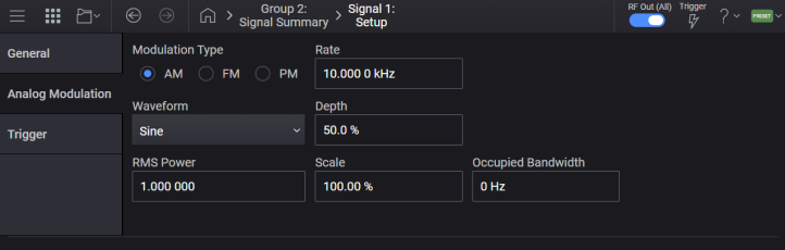
Sets the analog modulation type to Amplitude, Frequency, or Phase modulation.
|
GUI Location |
Signals > General tab > Mode set to Analog Modulation > Analog Analog Modulation tab > AM, FM, or PM |
|
SCPI Command |
[:SOURce]:GROup<group>:SIGNal<signal>:AMODulation:TYPE AM|FM|PM [:SOURce]:GROup<group>:SIGNal<signal>:AMODulation:TYPE? |
|
SCPI Example |
GRO:SIGN:AMOD:TYPE AM GRO:SIGN:AMOD:TYPE? |
|
Preset |
AM |
|
Choices |
AM | FM | PM |
|
State Saved |
Yes |
|
Backwards Compatibility SCPI |
The following commands are not recommended. They are for the convenience of users with existing remote programs developed for earlier versions of the signal generator or ported from a similar product. Alias [:SOURce]:SIGNal[1]:AMODulation:TYPE to :SOURce:GROup1:SIGNal1:AMODulation:TYPE Alias [:SOURce]:SIGNal2:AMODulation:TYPE to :SOURce:GROup2:SIGNal1:AMODulation:TYPE |
|
Initial S/W Revision |
A.01.00 |
|
Modified S/W Revision |
A.09.00 Added :GROup keyword |
Sets the AM waveform type.
|
GUI Location |
Signals > Mode set to Analog Modulation > Analog Modulation tab > Modulation Type set to AM > Waveform |
|
SCPI Command |
[:SOURce]:GROup<group>:SIGNal<signal>:AM:SHAPe SINE|DUAL|TRIangle|RUP|RDOWn|SQUare [:SOURce]:GROup<group>:SIGNal<signal>:AM:SHAPe? |
|
SCPI Example |
GRO:SIGN:AM:SHAP TRI GRO:SIGN:AM:SHAP? |
|
Preset |
SINE |
|
State Saved |
Yes |
|
Choices |
Sine | Dual-sine | Triangle | Ramp Up | Ramp Down | Square |
|
Backwards Compatibility SCPI |
The following commands are not recommended. They are for the convenience of users with existing remote programs developed for earlier versions of the signal generator or ported from a similar product. Alias [:SOURce]:SIGNal[1]:AM:SHAPe to :SOURce:GROup1:SIGNal1:AM:SHAPe Alias [:SOURce]:SIGNal2:AM:SHAPe to :SOURce:GROup2:SIGNal1:AM:SHAPe |
|
Initial S/W Revision |
A.01.00 |
|
Modified S/W Revision |
A.09.00 Added :GROup keyword |
Sets the rate of modulation for the AM mode.
|
GUI Location |
Signals > Mode set to Analog Modulation > Analog Modulation tab > Modulation Type set to AM > Rate |
|
SCPI Command |
[:SOURce]:GROup<group>:SIGNal<signal>:AM:FREQuency <freq> [:SOURce]:GROup<group>:SIGNal<signal>:AM:FREQuency? |
|
SCPI Example |
GRO:SIGN:AM:FREQ 10.5 kHz GRO:SIGN:AM:FREQ? |
|
Preset |
10 kHz |
|
State Saved |
Yes |
|
Min |
1 Hz |
|
Max |
Sine: Bandwidth/2 Others: Bandwidth/16 For bandwidth, see Vector Modulation Bandwidth Limitations. |
|
Backwards Compatibility SCPI |
The following commands are not recommended. They are for the convenience of users with existing remote programs developed for earlier versions of the signal generator or ported from a similar product. Alias [:SOURce]:SIGNal[1]:AM:FREQuency to :SOURce:GROup1:SIGNal1:AM:FREQuency Alias [:SOURce]:SIGNal2:AM:FREQuency to :SOURce:GROup2:SIGNal1:AM:FREQuency |
|
Initial S/W Revision |
A.01.00 |
|
Modified S/W Revision |
A.09.00 Added :GROup keyword |
Sets rate (frequency) for the second sine of Dual-Sine.
|
GUI Location |
Signals > Mode set to Analog Modulation > Analog Modulation tab > Modulation Type set to AM > Waveform set to Dual-Sine > Rate 2 |
|
SCPI Command |
[:SOURce]:GROup<group>:SIGNal<signal>:AM:DSINe:FREQuency <freq> [:SOURce]:GROup<group>:SIGNal<signal>:AM:DSINe:FREQuency? |
|
SCPI Example |
GRO:SIGN:AM:DSIN:FREQ 10.5 kHz GRO:SIGN:AM:DSIN:FREQ? |
|
Preset |
10 kHz |
|
State Saved |
Yes |
|
Min |
1 Hz |
|
Max |
Bandwidth/16 For bandwidth, see Vector Modulation Bandwidth Limitations. |
|
Backwards Compatibility SCPI |
The following commands are not recommended. They are for the convenience of users with existing remote programs developed for earlier versions of the signal generator or ported from a similar product. Alias [:SOURce]:SIGNal[1]:AM:DSINe:FREQuency to :SOURce:GROup1:SIGNal1:AM:DSINe:FREQuency Alias [:SOURce]:SIGNal2:AM:DSINe:FREQuency to :SOURce:GROup2:SIGNal1:AM:DSINe:FREQuency |
|
Initial S/W Revision |
A.01.00 |
|
Modified S/W Revision |
A.09.00 Added :GROup keyword |
Sets the modulation depth for the AM mode in percent.
|
GUI Location |
Signals > Mode set to Analog Modulation > Analog Modulation tab > Modulation Type set to AM > Depth |
|
SCPI Command |
[:SOURce]:GROup<group>:SIGNal<signal>:AM[:DEPTh] <real> [:SOURce]:GROup<group>:SIGNal<signal>:AM[:DEPTh]? |
|
SCPI Example |
GRO:SIGN:AM 30 GRO:SIGN:AM? |
|
Preset |
50 |
|
State Saved |
Yes |
|
Min |
0 |
|
Max |
100 |
|
Backwards Compatibility SCPI |
The following commands are not recommended. They are for the convenience of users with existing remote programs developed for earlier versions of the signal generator or ported from a similar product. Alias [:SOURce]:SIGNal[1]:AM[:DEPTh] to :SOURce:GROup1:SIGNal1:AM[:DEPTh] Alias [:SOURce]:SIGNal2:AM[:DEPTh] to :SOURce:GROup2:SIGNal1:AM[:DEPTh] |
|
Initial S/W Revision |
A.01.00 |
|
Modified S/W Revision |
A.09.00 Added :GROup keyword |
Sets relative amplitude for the second sine of a Dual-Sine waveform.
|
GUI Location |
Signals > Mode set to Analog Modulation > Analog Modulation tab >Modulation Type > AM > Waveform set to Dual-Sine > Amplitude 2 |
|
SCPI Command |
[:SOURce]:GROup<group>:SIGNal<signal>:AM:DSINe:AMPLitude:PERCent <real> [:SOURce]:GROup<group>:SIGNal<signal>:AM:DSINe:AMPLitude:PERCent? |
|
SCPI Example |
GRO:SIGN:AM:DSIN:AMPL:PERC 5 GRO:SIGN:AM:DSIN:AMPL:PERC? |
|
Preset |
50 |
|
State Saved |
Yes |
|
Min |
0 |
|
Max |
100 |
|
Initial S/W Revision |
A.01.00 |
|
Backwards Compatibility SCPI |
The following commands are not recommended. They are for the convenience of users with existing remote programs developed for earlier versions of the signal generator or ported from a similar product. Alias [:SOURce]:SIGNal[1]:AM:DSINe:AMPLitude:PERCent to :SOURce:GROup1:SIGNal1:AM:DSINe:AMPLitude:PERCent Alias [:SOURce]:SIGNal2:AM:DSINe:AMPLitude:PERCent to :SOURce:GROup2:SIGNal1:AM:DSINe:AMPLitude:PERCent |
|
Initial S/W Revision |
A.01.00 |
|
Modified S/W Revision |
A.09.00 Added :GROup keyword |
Sets the RMS power of AM signal.
When AM signal is generated (or recalculated), this value is set based on the generated signal.
|
GUI Location |
Signals > Mode set to Analog Modulation > Analog Modulation tab >Modulation Type set to AM > RMS Power |
|
SCPI Command |
[:SOURce]:GROup<group>:SIGNal<signal>:AM:RMS <real> [:SOURce]:GROup<group>:SIGNal<signal>:AM:RMS? |
|
SCPI Example |
GRO:SIGN:AM:RMS 1 GRO:SIGN:AM:RMS? |
|
Preset |
1 |
|
State Saved |
Yes |
|
Min |
0.1 |
|
Max |
1.414213562 |
|
Resolution |
0.000000001 |
|
Initial S/W Revision |
A.15.00 |
Sets the scale factor of AM signal.
When AM signal is generated (or recalculated), this value is set based on the generated signal.
|
GUI Location |
Signals > Mode set to Analog Modulation > Analog Modulation tab >Modulation Type set to AM > Scale |
|
SCPI Command |
[:SOURce]:GROup<group>:SIGNal<signal>:AM:SCALe <real> [:SOURce]:GROup<group>:SIGNal<signal>:AM:SCALe? |
|
SCPI Example |
GRO:SIGN:AM:SCAL 100 GRO:SIGN:AM:SCAL? |
|
Preset |
100 For M9484C: 70 |
|
State Saved |
Yes |
|
Min |
1 |
|
Max |
100 |
|
Resolution |
0.01 |
|
Initial S/W Revision |
A.15.00 |
| Modified S/W Version | A.16.00 - Changed the Preset from 100 to 70 for M9484C. |
Sets the occupied bandwidth of AM signal.
When AM signal is generated (or recalculated), this value is set to the same value as Sample Rate.
|
GUI Location |
Signals > Mode set to Analog Modulation > Analog Modulation tab >Modulation Type set to AM > Occupied Bandwidth |
|
SCPI Command |
[:SOURce]:GROup<group>:SIGNal<signal>:AM:OBWidth <freq> [:SOURce]:GROup<group>:SIGNal<signal>:AM:OBWidth? |
|
SCPI Example |
GRO:SIGN:AM:OBW 140 kHz GRO:SIGN:AM:OBW? |
|
Preset |
0 |
|
State Saved |
Yes |
|
Min |
0 Hz |
|
Max |
BW For BW, see Vector Modulation Bandwidth Limitations table. |
|
Resolution |
1 Hz |
|
Initial S/W Revision |
A.15.00 |
Sets the FM waveform type.
|
GUI Location |
Signals > Mode set to Analog Modulation > Analog Modulation tab > Modulation Type FM > Waveform |
|
SCPI Command |
[:SOURce]:GROup<group>:SIGNal<signal>:FM:SHAPe SINE|DUAL|TRIangle|RUP|RDOWn|SQUare [:SOURce]:GROup<group>:SIGNal<signal>:FM:SHAPe? |
|
SCPI Example |
GRO:SIGN:FM:SHAP TRI GRO:SIGN:FM:SHAP? |
|
Preset |
SINE |
|
State Saved |
Yes |
|
Choices |
Sine | Dual-sine | Triangle | Ramp Up | Ramp Down | Square |
|
Backwards Compatibility SCPI |
The following commands are not recommended. They are for the convenience of users with existing remote programs developed for earlier versions of the signal generator or ported from a similar product. Alias [:SOURce]:SIGNal[1]:FM:SHAPe to :SOURce:GROup1:SIGNal1:FM:SHAPe Alias [:SOURce]:SIGNal2:FM:SHAPe to :SOURce:GROup2:SIGNal1:FM:SHAPe |
|
Initial S/W Revision |
A.01.00 |
|
Modified S/W Revision |
A.09.00 Added :GROup keyword |
Sets the rate of modulation for the FM mode.
|
GUI Location |
Signals > Mode set to Analog Modulation > Analog Modulation tab > Modulation Type set to FM > Rate |
|
SCPI Command |
[:SOURce]:GROup<group>:SIGNal<signal>:FM:FREQuency <freq> [:SOURce]:GROup<group>:SIGNal<signal>:FM:FREQuency? |
|
SCPI Example |
GRO:SIGN:FM:FREQ 10.5 kHz GRO:SIGN:FM:FREQ? |
|
Preset |
10 kHz |
|
State Saved |
Yes |
|
Min |
1 Hz |
|
Max |
Sine: Bandwidth/4 Others: Bandwidth/16 For bandwidth, see Vector Modulation Bandwidth Limitations. |
|
Backwards Compatibility SCPI |
The following commands are not recommended. They are for the convenience of users with existing remote programs developed for earlier versions of the signal generator or ported from a similar product. Alias [:SOURce]:SIGNal[1]:FM:FREQuency to :SOURce:GROup1:SIGNal1:FM:FREQuency Alias [:SOURce]:SIGNal2:FM:FREQuency to :SOURce:GROup2:SIGNal1:FM:FREQuency |
|
Initial S/W Revision |
A.01.00 |
|
Modified S/W Revision |
A.09.00 Added :GROup keyword |
Sets the FM Rate for a the second sine of a Dual-Sine waveform.
|
GUI Location |
Signals > Mode set to Analog Modulation > Analog Modulation tab >Modulation Type set to FM > Waveform set to Dual-Sine > Rate 2 |
|
SCPI Command |
[:SOURce]:GROup<group>:SIGNal<signal>:FM:DSINe:FREQuency <freq> [:SOURce]:GROup<group>:SIGNal<signal>:FM:DSINe:FREQuency? |
|
SCPI Example |
GRO:SIGN:FM:DSIN:FREQ 10.5 kHz GRO:SIGN:FM:DSIN:FREQ? |
|
Preset |
10 kHz |
|
State Saved |
Yes |
|
Min |
1 Hz |
|
Max |
Bandwidth/16 For bandwidth, see Vector Modulation Bandwidth Limitations. |
|
Backwards Compatibility SCPI |
The following commands are not recommended. They are for the convenience of users with existing remote programs developed for earlier versions of the signal generator or ported from a similar product. Alias [:SOURce]:SIGNal[1]:FM:DSINe:FREQuency to :SOURce:GROup1:SIGNal1:FM:DSINe:FREQuency Alias [:SOURce]:SIGNal2:FM:DSINe:FREQuency to :SOURce:GROup2:SIGNal1:FM:DSINe:FREQuency |
|
Initial S/W Revision |
A.01.00 |
|
Modified S/W Revision |
A.09.00 Added :GROup keyword |
Sets the frequency modulation deviation.
|
GUI Location |
Signals > Mode set to Analog Modulation > Analog Modulation tab >Modulation Type set to FM > Deviation |
|
SCPI Command |
[:SOURce]:GROup<group>:SIGNal<signal>:FM[:DEViation] <freq> [:SOURce]:GROup<group>:SIGNal<signal>:FM[:DEViation]? |
|
SCPI Example |
GRO:SIGN:FM 20 GRO:SIGN:FM? |
|
Preset |
0.5 Hz |
|
State Saved |
Yes |
|
Min |
0 Hz |
|
Max |
50 MHz |
|
Backwards Compatibility SCPI |
The following commands are not recommended. They are for the convenience of users with existing remote programs developed for earlier versions of the signal generator or ported from a similar product. Alias [:SOURce]:SIGNal[1]:FM[:DEViation] to :SOURce:GROup1:SIGNal1:FM[:DEViation] Alias [:SOURce]:SIGNal2:FM[:DEViation] to :SOURce:GROup2:SIGNal1:FM[:DEViation] |
|
Initial S/W Revision |
A.01.00 |
|
Modified S/W Revision |
A.09.00 Added :GROup keyword |
Sets relative amplitude for the second sine of a Dual-Sine waveform.
|
GUI Location |
Signals > Mode set to Analog Modulation > Analog Modulation tab > Modulation Type set to FM > Waveform set to Dual-Sine > Amplitude 2 |
|
SCPI Command |
[:SOURce]:GROup<group>:SIGNal<signal>:FM:DSINe:AMPLitude:PERCent <real> [:SOURce]:GROup<group>:SIGNal<signal>:FM:DSINe:AMPLitude:PERCent? |
|
SCPI Example |
GRO:SIGN:FM:DSIN:AMPL:PERC 5 GRO:SIGN:FM:DSIN:AMPL:PERC? |
|
Preset |
50 |
|
State Saved |
Yes |
|
Min |
0 |
|
Max |
100 |
|
Backwards Compatibility SCPI |
The following commands are not recommended. They are for the convenience of users with existing remote programs developed for earlier versions of the signal generator or ported from a similar product. Alias [:SOURce]:SIGNal[1]:FM:DSINe:AMPLitude:PERCent to :SOURce:GROup1:SIGNal1:FM:DSINe:AMPLitude:PERCent Alias [:SOURce]:SIGNal2:FM:DSINe:AMPLitude:PERCent to :SOURce:GROup2:SIGNal1:FM:DSINe:AMPLitude:PERCent |
|
Initial S/W Revision |
A.01.00 |
|
Modified S/W Revision |
A.09.00 Added :GROup keyword |
Sets the RMS of FM signal.
When FM signal is generated (or recalculated), this value is set based on the generated signal.
|
GUI Location |
Signals > Mode set to Analog Modulation > Analog Modulation tab > Modulation Type set to FM > RMS Power |
|
SCPI Command |
[:SOURce]:GROup<group>:SIGNal<signal>:FM:RMS <real> [:SOURce]:GROup<group>:SIGNal<signal>:FM:RMS? |
|
SCPI Example |
GRO:SIGN:FM:RMS 1 GRO:SIGN:FM:RMS? |
|
Preset |
1 |
|
State Saved |
Yes |
|
Min |
0.1 |
|
Max |
1.414213562 |
|
Resolution |
0.000000001 |
|
Initial S/W Revision |
A.15.00 |
Sets the scale factor of FM signal.
When FM signal is generated (or recalculated), this value is set based on the generated signal.
|
GUI Location |
Signals > Mode set to Analog Modulation > Analog Modulation tab > Modulation Type set to FM > Scale |
|
SCPI Command |
[:SOURce]:GROup<group>:SIGNal<signal>:FM:SCALe <real> [:SOURce]:GROup<group>:SIGNal<signal>:FM:SCALe? |
|
SCPI Example |
GRO:SIGN:FM:SCAL 100 GRO:SIGN:FM:SCAL? |
|
Preset |
100 For M9484C: 70 |
|
State Saved |
Yes |
|
Min |
1 |
|
Max |
100 |
|
Resolution |
0.01 |
|
Initial S/W Revision |
A.15.00 |
| Modified S/W Version | A.16.00 - Changed the Preset from 100 to 70 for M9484C. |
Sets the occupied bandwidth of FM signal.
When FM signal is generated (or recalculated), this value is set to the same value as Sample Rate.
|
GUI Location |
Signals > Mode set to Analog Modulation > Analog Modulation tab > Modulation Type set to FM > Occupied Bandwidth |
|
SCPI Command |
[:SOURce]:GROup<group>:SIGNal<signal>:FM:OBWidth <freq> [:SOURce]:GROup<group>:SIGNal<signal>:FM:OBWidth? |
|
SCPI Example |
GRO:SIGN:FM:OBW 140 kHz GRO:SIGN:FM:OBW? |
|
Preset |
0 |
|
State Saved |
Yes |
|
Min |
0 Hz |
|
Max |
BW For BW, see Vector Modulation Bandwidth Limitations table. |
|
Resolution |
1 Hz |
|
Initial S/W Revision |
A.15.00 |
Sets the PM waveform type.
|
GUI Location |
Signals > Mode set to Analog Modulation > Analog Modulation tab > Modulation Type > PM > Waveform |
|
SCPI Command |
[:SOURce]:GROup<group>:SIGNal<signal>:PM:SHAPe SINE|DUAL|TRIangle|RUP|RDOWn|SQUare [:SOURce]:GROup<group>:SIGNal<signal>:PM:SHAPe? |
|
SCPI Example |
GRO:SIGN:PM:SHAP TRI GRO:SIGN:PM:SHAP? |
|
Preset |
SINE |
|
State Saved |
Yes |
|
Choices |
Sine | Dual-sine | Triangle | Ramp Up | Ramp Down | Square |
|
Backwards Compatibility SCPI |
The following commands are not recommended. They are for the convenience of users with existing remote programs developed for earlier versions of the signal generator or ported from a similar product. Alias [:SOURce]:SIGNal[1]:PM:SHAPe to :SOURce:GROup1:SIGNal1:PM:SHAPe Alias [:SOURce]:SIGNal2:PM:SHAPe to :SOURce:GROup2:SIGNal1:PM:SHAPe |
|
Initial S/W Revision |
A.01.00 |
|
Modified S/W Revision |
A.09.00 Added :GROup keyword |
Sets the rate of modulation for the PM mode.
|
GUI Location |
Signals > Mode set to Analog Modulation > Analog Modulation tab > Modulation Type set to PM > Rate |
|
SCPI Command |
[:SOURce]:GROup<group>:SIGNal<signal>:PM:FREQuency <freq> [:SOURce]:GROup<group>:SIGNal<signal>:PM:FREQuency? |
|
SCPI Example |
GRO:SIGN:PM:FREQ 10.5 kHz GRO:SIGN:PM:FREQ? |
|
Preset |
10 kHz |
|
State Saved |
Yes |
|
Min |
1 Hz |
|
Max |
Sine: Bandwidth/4 Others: Bandwidth/16 For bandwidth, see Vector Modulation Bandwidth Limitations. |
|
Backwards Compatibility SCPI |
The following commands are not recommended. They are for the convenience of users with existing remote programs developed for earlier versions of the signal generator or ported from a similar product. Alias [:SOURce]:SIGNal[1]:PM:FREQuency to :SOURce:GROup1:SIGNal1:PM:FREQuency Alias [:SOURce]:SIGNal2:PM:FREQuency to :SOURce:GROup2:SIGNal1:PM:FREQuency |
|
Initial S/W Revision |
A.01.00 |
|
Modified S/W Revision |
A.09.00 Added :GROup keyword |
Sets the PM Rate for a the second sine of a Dual-Sine waveform.
|
GUI Location |
Signals > Mode set to Analog Modulation > Analog Modulation tab > Modulation Type set to PM > Waveform set to Dual-Sine > Rate 2 |
|
SCPI Command |
[:SOURce]:GROup<group>:SIGNal<signal>:PM:DSINe:FREQuency <freq> [:SOURce]:GROup<group>:SIGNal<signal>:PM:DSINe:FREQuency? |
|
SCPI Example |
GRO:SIGN:PM:DSIN:FREQ 10.5 kHz GRO:SIGN:PM:DSIN:FREQ? |
|
Preset |
10 kHz |
|
State Saved |
Yes |
|
Min |
1 Hz |
|
Max |
Bandwidth/16 For bandwidth, see Vector Modulation Bandwidth Limitations. |
|
Initial S/W Revision |
A.01.00 |
|
Backwards Compatibility SCPI |
The following commands are not recommended. They are for the convenience of users with existing remote programs developed for earlier versions of the signal generator or ported from a similar product. Alias [:SOURce]:SIGNal[1]:PM:DSINe:FREQuency to :SOURce:GROup1:SIGNal1:PM:DSINe:FREQuency Alias [:SOURce]:SIGNal2:PM:DSINe:FREQuency to :SOURce:GROup2:SIGNal1:PM:DSINe:FREQuency |
|
Initial S/W Revision |
A.01.00 |
|
Modified S/W Revision |
A.09.00 Added :GROup keyword |
Sets the phase modulation deviation in radian.
|
GUI Location |
Signals > Mode set to Analog Modulation > Analog Modulation tab > Modulation Type set to PM > Deviation |
|
SCPI Command |
[:SOURce]:GROup<group>:SIGNal<signal>:PM[:DEViation] <real> [:SOURce]:GROup<group>:SIGNal<signal>:PM[:DEViation]? |
|
SCPI Example |
GRO:SIGN:PM 7 GRO:SIGN:PM? |
|
Preset |
0.5 |
|
State Saved |
Yes |
|
Min |
0 |
|
Max |
10 |
|
Backwards Compatibility SCPI |
The following commands are not recommended. They are for the convenience of users with existing remote programs developed for earlier versions of the signal generator or ported from a similar product. Alias [:SOURce]:SIGNal[1]:PM[:DEViation] to :SOURce:GROup1:SIGNal1:PM[:DEViation] Alias [:SOURce]:SIGNal2:PM[:DEViation] to :SOURce:GROup2:SIGNal1:PM[:DEViation] |
|
Initial S/W Revision |
A.01.00 |
|
Modified S/W Revision |
A.09.00 Added :GROup keyword |
Sets relative amplitude for the second sine of a Dual-Sine waveform.
|
GUI Location |
Signals > Mode set to Analog Modulation > Analog Modulation tab > Modulation Type set to PM > Waveform set to Dual-Sine > Amplitude 2 |
|
SCPI Command |
[:SOURce]:GROup<group>:SIGNal<signal>:PM:DSINe:AMPLitude:PERCent <real> [:SOURce]:GROup<group>:SIGNal<signal>:PM:DSINe:AMPLitude:PERCent? |
|
SCPI Example |
GRO:SIGN:PM:DSIN:AMPL:PERC 5 GRO:SIGN:PM:DSIN:AMPL:PERC? |
|
Preset |
50 |
|
State Saved |
Yes |
|
Min |
0 |
|
Max |
100 |
|
Backwards Compatibility SCPI |
The following commands are not recommended. They are for the convenience of users with existing remote programs developed for earlier versions of the signal generator or ported from a similar product. Alias [:SOURce]:SIGNal[1]:PM:DSINe:AMPLitude:PERCent to :SOURce:GROup1:SIGNal1:PM:DSINe:AMPLitude:PERCent Alias [:SOURce]:SIGNal2:PM:DSINe:AMPLitude:PERCent to :SOURce:GROup2:SIGNal1:PM:DSINe:AMPLitude:PERCent |
|
Initial S/W Revision |
A.01.00 |
|
Modified S/W Revision |
A.09.00 Added :GROup keyword |
Sets the RMS of PM signal.
When PM signal is generated (or recalculated), this value is set based on the generated signal.
|
GUI Location |
Signals > Mode set to Analog Modulation > Analog Modulation tab > Modulation Type set to PM > RMS Power |
|
SCPI Command |
[:SOURce]:GROup<group>:SIGNal<signal>:PM:RMS <real> [:SOURce]:GROup<group>:SIGNal<signal>:PM:RMS? |
|
SCPI Example |
GRO:SIGN:PM:RMS 1 GRO:SIGN:PM:RMS? |
|
Preset |
1 |
|
State Saved |
Yes |
|
Min |
0.1 |
|
Max |
1.414213562 |
|
Resolution |
0.000000001 |
|
Initial S/W Revision |
A.15.00 |
Sets the scale factor of PM signal.
When PM signal is generated (or recalculated), this value is set based on the generated signal.
|
GUI Location |
Signals > Mode set to Analog Modulation > Analog Modulation tab > Modulation Type set to PM > Scale |
|
SCPI Command |
[:SOURce]:GROup<group>:SIGNal<signal>:PM:SCALe <real> [:SOURce]:GROup<group>:SIGNal<signal>:PM:SCALe? |
|
SCPI Example |
GRO:SIGN:PM:SCAL 100 GRO:SIGN:PM:SCAL? |
|
Preset |
100 For M9484C: 70 |
|
State Saved |
Yes |
|
Min |
1 |
|
Max |
100 |
|
Resolution |
0.01 |
|
Initial S/W Revision |
A.15.00 |
| Modified S/W Version | A.16.00 - Changed the Preset from 100 to 70 for M9484C |
Sets the occupied bandwidth of PM signal.
When PM signal is generated (or recalculated), this value is set to the same value as Sample Rate.
|
GUI Location |
Signals > Mode set to Analog Modulation > Analog Modulation tab > Modulation Type set to PM > Occupied Bandwidth |
|
SCPI Command |
[:SOURce]:GROup<group>:SIGNal<signal>:PM:OBWidth <freq> [:SOURce]:GROup<group>:SIGNal<signal>:PM:OBWidth? |
|
SCPI Example |
GRO:SIGN:PM:OBW 140 kHz GRO:SIGN:PM:OBW? |
|
Preset |
0 |
|
State Saved |
Yes |
|
Min |
0 Hz |
|
Max |
BW For BW, see Vector Modulation Bandwidth Limitations table. |
|
Resolution |
1 Hz |
|
Initial S/W Revision |
A.15.00 |
This capability requires license model N7621APPC.
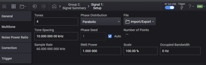
The number of samples of a Multitone signal is determined by Tones and Tone Spacing when the required BW is much smaller than the maximum sample rate. However, when the required BW becomes larger and the max Sample Rate needs to be used, the number of samples of Multitone signal is determined mainly by the greatest common divisor (GCD) of the max Sample Rate and Tone Spacing.
For example, assuming the max Sample Rate is 2.56 GHz, if Tones and Tone Spacing are set to 201 and 12,111,111 Hz respectively, the GCD is 1 Hz, which requires the signal to be 1 sec long in time. Therefore 2.56 G samples are required, which is far larger points than the size of internal buffer array (64 M samples). In this case, an error is issued, and Multitone signal is not generated.
If the tone spacing is changed to 12,111,100 Hz, the GCD becomes 100 Hz and the signal length will reduce to 0.01 sec. It is 25.6 M samples and small enough to fit in the buffer.
Remote command only.
This is an action command that imports the tone table data from the multitone file. The multitone file is a text file that consists of four columns separated by spaces, tabs, or commas. The four columns are status, frequency (Hz), relative amplitude (dB) and phase (degree). Only UTF-8 encoding with and without BOM is supported.
The query returns the name of either the most recently used file in this command or the most recently exported tone table file.
The following is the example of the multitone file in which five tones are defined with 1.0 MHz spacing. The relative amplitude of tones are all zero.
1 -2000000 0 40.11
1 -1000000 0 167.88
1 0 0 277.88
1 1000000 0 236.63
1 2000000 0 155.84
The multitone file needs to satisfy the following conditions, otherwise it is rejected with an error message.
The tone frequencies in the file need to be equally spaced. The tone frequencies are rounded to the resolution of Tone Spacing before the check.
The bandwidth of tones, the maximum - the minimum tone frequencies, is less than or equal to the vector modulation bandwidth that varies based on the channel frequency. See Vector Modulation Bandwidth Limitations.
The number of Tones and Tone Spacing need to be within their specified ranges.
The center of tones is at frequency zero.
The tone frequencies are in the ascending order.
The values are separate with a single space. Consecutive multiple spaces are not allowed.
The RMS of generated waveform is not too small. For example, when many tones have the same phase, an error message appears.
The MTONE MSUS can be used to specify the multitone file. See File Location and Default Folders for more details about MTONE MSUS. With MTONE, you can send or select a multitone file as shown below.
:MMEMory:DATA "MTONE:myTones", ...
:SIGNal:MTONe:ARB:SETup "MTONE:myTones"
|
SCPI Command |
[:SOURce]:GROup<group>:SIGNal<signal>:MTONe:ARB:SETup "<filename>" [:SOURce]:GROup<group>:SIGNal<signal>:MTONe:ARB:SETup? |
|
SCPI Example |
GRO:SIGN:MTON:ARB:SET "MTONE:myTones" |
|
State Saved |
No |
|
Backwards Compatibility SCPI |
The following commands are not recommended. They are for the convenience of users with existing remote programs developed for earlier versions of the signal generator or ported from a similar product. Alias [:SOURce]:SIGNal[1]:MTONe:ARB:SETup to :SOURce:GROup1:SIGNal1:MTONe:ARB:SETup Alias [:SOURce]:SIGNal2:MTONe:ARB:SETup to :SOURce:GROup2:SIGNal1:MTONe:ARB:SETup Alias [:SOURce]:RADio:MTONe:ARB:SETup to :SOURce:GROup1:SIGNal1:MTONe:ARB:SETup Alias [:SOURce]:RADio:MTONe:ARB:SETup? to :SOURce:GROup1:SIGNal1:MTONe:ARB:SETup? |
|
Initial S/W Revision |
A.08.00 |
|
Modified S/W Revision |
A.09.00 Added :GROup keyword A.18.00 Added query and BWC commands |
Remote command only.
Query only. Returns values of all tones included in the internal tone table.
|
SCPI Command |
[:SOURce]:GROup<group>:SIGNal<signal>:MTONe:ARB:SETup:TABLe? |
|
SCPI Example |
GRO:SIGN:MTON:ARB:SET:TABL? |
| Notes | Query returns values in the order of state, frequency (Hz), relative amplitude (dB), and phase (degree) for each tone in the table. For example, if the tone table includes 10 tones, then 10 x 4 = 40 values are returned. |
|
State Saved |
No |
|
Backwards Compatibility SCPI |
The following commands are not recommended. They are for the convenience of users with existing remote programs developed for earlier versions of the signal generator or ported from a similar product. Alias [:SOURce]:SIGNal[1]:MTONe:ARB:SETup:TABLe? to :SOURce:GROup1:SIGNal1:MTONe:ARB:SETup:TABLe? Alias [:SOURce]:SIGNal2:MTONe:ARB:SETup:TABLe? to :SOURce:GROup2:SIGNal1:MTONe:ARB:SETup:TABLe? |
|
Initial S/W Revision |
A.08.00 |
|
Modified S/W Revision |
A.09.00 Added :GROup keyword |
Remote command only.
This command is provided for compatibility with earlier versions of instrument software, creating and configuring an internal tone table for signal 1 of group 1.
|
SCPI Command |
[:SOURce]:RADio:MTONe:ARB:SETup:TABLe <freq_spacing>, <num_tones>,<phase1>,<state1>,<phase2>,<state2>,... [:SOURce]:RADio:MTONe:ARB:SETup:TABLe? |
|
SCPI Example |
RAD:MTON:ARB:SET:TABL 10000,4, 0,1,0,1,0,1,0,1 RAD:MTON:ARB:SET:TABL? |
| Notes |
Command parameters:
Query returns values in the order of frequency (Hz), relative amplitude (dB), phase (degree), and state for each tone in the table. For example, if the tone table includes 10 tones, 10 x 4 = 40 values are returned. |
|
State Saved |
No |
|
Initial S/W Revision |
A.18.00 |
Sets the number of tones. Setting this value regenerates tones with 0 dB amplitude and randomly calculated phases.
Values set with Setup are discarded.
|
GUI Location |
Signals > Mode set to Multitone > Multitone tab >Tones |
|
SCPI Command |
[:SOURce]:GROup<group>:SIGNal<signal>:MTONe:ARB:NTONes <integer> [:SOURce]:GROup<group>:SIGNal<signal>:MTONe:ARB:NTONes? |
|
SCPI Example |
GRO:SIGN:MTON:ARB:NTON 2 GRO:SIGN:MTON:ARB:NTON? |
|
Preset |
4 |
|
State Saved |
Yes |
|
Min |
2 |
|
Max |
For M9484C:
1000
200,001
10,000,001 |
|
Resolution |
1 |
|
Backwards Compatibility SCPI |
The following commands are not recommended. They are for the convenience of users with existing remote programs developed for earlier versions of the signal generator or ported from a similar product. [:SOURce]:GROup<group>:SIGNal<signal>:MTONe:ARB:SETup:TABLe:NTONes Alias [:SOURce]:SIGNal[1]:MTONe:ARB:SETup:TABLe:NTONes to :SOURce:GROup1:SIGNal1:MTONe:ARB:SETup:TABLe:NTONes Alias [:SOURce]:SIGNal2:MTONe:ARB:SETup:TABLe:NTONes to :SOURce:GROup2:SIGNal1:MTONe:ARB:SETup:TABLe:NTONes Alias [:SOURce]:SIGNal[1]:MTONe:ARB:NTONes to :SOURce:GROup1:SIGNal1:MTONe:ARB:NTONes Alias [:SOURce]:SIGNal2:MTONe:ARB:NTONes to :SOURce:GROup2:SIGNal1:MTONe:ARB:NTONes |
|
Initial S/W Revision |
A.01.00 |
|
Modified S/W Revision |
A.08.00 Changed the SCPI command from [:SOURce]:SIGNal<signal>:MTONe:ARB:NTONes, changed max from 1000 A.09.00 Added :GROup keyword A.14.00 Changed the SCPI command from [:SOURce]:GROup<group>:SIGNal<signal>:MTONe:ARB:SETup:TABLe:NTONes A.15.00 Changed max value (200001) for M9484C |
Sets the frequency spacing between the tones. Setting this value regenerates tones with 0 dB amplitude and randomly calculated phases.
Values set with Setup are discarded.
|
GUI Location |
Signals > Mode set to Multitone > Multitone tab > Tone Spacing |
|
SCPI Command |
[:SOURce]:GROup<group>:SIGNal<signal>:MTONe:ARB:FSPacing <freq> [:SOURce]:GROup<group>:SIGNal<signal>:MTONe:ARB:FSPacing? |
|
SCPI Example |
GRO:SIGN:MTON:ARB:FSP 128 GRO:SIGN:MTON:ARB:FSP? |
|
Preset |
10 kHz |
|
State Saved |
Yes |
|
Min |
100 Hz |
|
Max |
Floor((Bandwidth in Vector Modulation Bandwidth Limitations)/((Number of Tones) - 1)/100) * 100 |
|
Resolution |
0.00001 Hz |
|
Backwards Compatibility SCPI |
[:SOURce]:SIGNal<signal>:MTONe:ARB:FSPacing <freq> [:SOURce]:SIGNal<signal>:MTONe:ARB:FSPacing? |
|
History |
Changed the SCPI command from [:SOURce]:SIGNal<signal>:MTONe:ARB:FSPacing at A.08.00 |
|
Backwards Compatibility SCPI |
The following commands are not recommended. They are for the convenience of users with existing remote programs developed for earlier versions of the signal generator or ported from a similar product. [:SOURce]:GROup<group>:SIGNal<signal>:MTONe:ARB:SETup:TABLe:FSPacing Alias [:SOURce]:SIGNal[1]:MTONe:ARB:SETup:TABLe:FSPacing to :SOURce:GROup1:SIGNal1:MTONe:ARB:SETup:TABLe:FSPacing Alias [:SOURce]:SIGNal2:MTONe:ARB:SETup:TABLe:FSPacing to :SOURce:GROup2:SIGNal1:MTONe:ARB:SETup:TABLe:FSPacing Alias [:SOURce]:SIGNal[1]:MTONe:ARB:FSPacing to :SOURce:GROup1:SIGNal1:MTONe:ARB:FSPacing Alias [:SOURce]:SIGNal2:MTONe:ARB:FSPacing to :SOURce:GROup2:SIGNal1:MTONe:ARB:FSPacing |
|
Initial S/W Revision |
A.01.00 |
|
Modified S/W Revision |
A.08.00 Changed the SCPI command from [:SOURce]:SIGNal<signal>:MTONe:ARB:FSPacing A.09.00 Added :GROup keyword A.14.00 Changed the SCPI command from [:SOURce]:GROup<group>:SIGNal<signal>:MTONe:ARB:SETup:TABLe:FSPacing |
Exports a multitone file. The values are equivalent to the results of the TABLe query command. The format of this file is the same as the Setup command.
There is no query form for this command.
|
GUI Location |
Signals > Mode set to Multitone > Multitone tab > Export Tone Table |
|
SCPI Command |
[:SOURce]:GROup<group>:SIGNal<signal>:MTONe:ARB:SETup:TABLe:EXPort <filename> |
|
SCPI Example |
:GRO:SIGN:MTON:ARB:SET:TABL:EXP "a.txt" |
| Backwards Compatibility SCPI | [:SOURce]:RADio:MTONe:ARB:SETup:STORe <filename> to [:SOURce]:GROup1:SIGNal1:MTONe:ARB:SETup:TABLe:EXPort <filename> |
|
Initial S/W Revision |
A.14.00 |
| Modified at S/W Revision | A.18.00 - Added BWC command |
Exports a multitone file including results of NPR. When NPR is off, the values are not valid. The values are equivalent to the results of the TABLe query command. The format of this file is the same as the Setup command.
|
GUI Location |
Signals > Mode set to Multitone > Multitone tab > Export Tone Table w/ NPR |
|
SCPI Command |
[:SOURce]:GROup<group>:SIGNal<signal>:MTONe:ARB:NPR:SETup:TABLe:EXPort <filename> |
|
SCPI Example |
:GRO:SIGN:MTON:ARB:NPR:SET:TABL:EXP "a.txt" |
|
Initial S/W Revision |
A.14.00 |
Exports a multitone file including results of Calibration. The values are equivalent to the results of the TABLe query command. The format of this file is the same as the Setup command.
|
GUI Location |
Signals > Mode set to Multitone > Multitone tab > Export Tone Table w/ Correction |
|
SCPI Command |
[:SOURce]:GROup<group>:SIGNal<signal>:MTONe:ARB:CORRection:SETup:TABLe:EXPort <filename> |
|
SCPI Example |
:GRO:SIGN:MTON:ARB:CORR:SET:TABL:EXP "a.txt" |
|
Initial S/W Revision |
A.14.00 |
Query only. Returns the number of sample points. The value becomes valid after generation.
|
SCPI Command |
[:SOURce]:GROup<group>:SIGNal<signal>:MTONe:ARB:SAMPles:COUNt? |
|
SCPI Example |
:GRO:SIGN:MTON:ARB:SAMP:COUN? |
|
Preset |
0 |
|
Initial S/W Revision |
A.14.00 |
Sets the phase distribution. After setting this value, phases of the tones are regenerated. After importing Tone Table, this value is set to User Defined. When this value is User Defined and phases of the tones are regenerated by changing another value, this value is set to Random.
|
GUI Location |
Signals > Mode set to Multitone > Multitone tab > Phase Distribution |
|
SCPI Command |
[:SOURce]:GROup<group>:SIGNal<signal>:MTONe:ARB:PHASe:DISTribution RANDom|CONStant|PARabolic|USER [:SOURce]:GROup<group>:SIGNal<signal>:MTONe:ARB:PHASe:DISTribution? |
|
SCPI Example |
:GRO:SIGN:MTON:ARB:PHAS:DIST PAR :GRO:SIGN:MTON:ARB:PHAS:DIST? |
|
Couplings |
Cannot be select User Defined from GUI and SCPI After importing tone table, the value is set to User Defined. In the case of User Defined, when the phase list is regenerated, this value is set to Random. |
|
Preset |
RANDom |
|
Range |
Random | Constant | Parabolic | User Defined |
|
State Saved |
Yes |
|
Initial S/W Revision |
A.14.00 |
Sets the phase seed setting. After setting this value, phases of the tones are regenerated.
|
GUI Location |
Signals > Mode set to Multitone > Multitone tab > Phase Seed |
|
SCPI Command |
[:SOURce]:GROup<group>:SIGNal<signal>:MTONe:ARB:PHASe:RANDom:SEED <integer> [:SOURce]:GROup<group>:SIGNal<signal>:MTONe:ARB:PHASe:RANDom:SEED? |
|
SCPI Example |
:GRO:SIGN:MTON:ARB:PHAS:SEED 1 :GRO:SIGN:MTON:ARB:PHAS:SEED? |
|
Preset |
1 |
|
Min |
0 |
|
Max |
2147483647 |
|
State Saved |
Yes |
|
Initial S/W Revision |
A.14.00 |
Turns the phase seed auto off or on. When the phase seed is changed, this value is turned off. After setting this value, phases of the tones are regenerated.
When on, the phase list is generated in the same way as A.12 or before.
|
GUI Location |
Signals > Mode set to Multitone > Multitone tab > Phase Seed Auto |
|
SCPI Command |
[:SOURce]:GROup<group>:SIGNal<signal>:MTONe:ARB:PHASe:RANDom:SEED:AUTO ON|OFF|1|0 [:SOURce]:GROup<group>:SIGNal<signal>:MTONe:ARB:PHASe:RANDom:SEED:AUTO? |
|
SCPI Example |
:GRO:SIGN:MTON:ARB:PHAS:RAND:SEED:AUTO 1 :GRO:SIGN:MTON:ARB:PHAS:RAND:SEED:AUTO? |
|
Couplings |
When the Phase Seed is changed, the value is set to false. |
|
Preset |
1 |
|
State Saved |
Yes |
|
Initial S/W Revision |
A.14.00 |
Sets the RMS of Multitone signal.
When Multitone signal is generated (or recalculated), this value is set based on the generated signal.
|
GUI Location |
Signals > Mode set to Multitone > Multitone tab > RMS Power |
|
SCPI Command |
[:SOURce]:GROup<group>:SIGNal<signal>:MTONe:RMS <real> [:SOURce]:GROup<group>:SIGNal<signal>:MTONe:RMS? |
|
SCPI Example |
GRO:SIGN:MTON:RMS 1 GRO:SIGN:MTON:RMS? |
|
Preset |
1 |
|
State Saved |
Yes |
|
Min |
0.1 |
|
Max |
1.414213562 |
|
Resolution |
0.000000001 |
|
Initial S/W Revision |
A.15.00 |
Sets the scale factor of Multitone signal.
When Multitone signal is generated (or recalculated), this value is set based on the generated signal.
|
GUI Location |
Signals > Mode set to Multitone > Multitone tab > Scale |
|
SCPI Command |
[:SOURce]:GROup<group>:SIGNal<signal>:MTONe:SCALe <real> [:SOURce]:GROup<group>:SIGNal<signal>:MTONe:SCALe? |
|
SCPI Example |
GRO:SIGN:MTON:SCAL 100 GRO:SIGN:MTON:SCAL? |
|
Preset |
100 For M9484C: 70 |
|
State Saved |
Yes |
|
Min |
1 |
|
Max |
100 |
|
Resolution |
0.01 |
|
Initial S/W Revision |
A.15.00 |
| Modified S/W Version | A.16.00 - Changed Preset from 100 to 70 for M9484C |
Sets the occupied bandwidth of Multitone signal.
When Multitone signal is generated (or recalculated), this value is set to the same value as (Tones - 1) x Tone Spacing.
|
GUI Location |
Signals > Mode set to Multitone > Multitone tab > Occupied Bandwidth |
|
SCPI Command |
[:SOURce]:GROup<group>:SIGNal<signal>:MTONe:OBWidth <freq> [:SOURce]:GROup<group>:SIGNal<signal>:MTONe:OBWidth? |
|
SCPI Example |
GRO:SIGN:MTON:OBW 140 kHz GRO:SIGN:MTON:OBW? |
|
Preset |
0 |
|
State Saved |
Yes |
|
Min |
0 Hz |
|
Max |
BW For BW, see Vector Modulation Bandwidth Limitations table. |
|
Resolution |
1 Hz |
|
Initial S/W Revision |
A.15.00 |
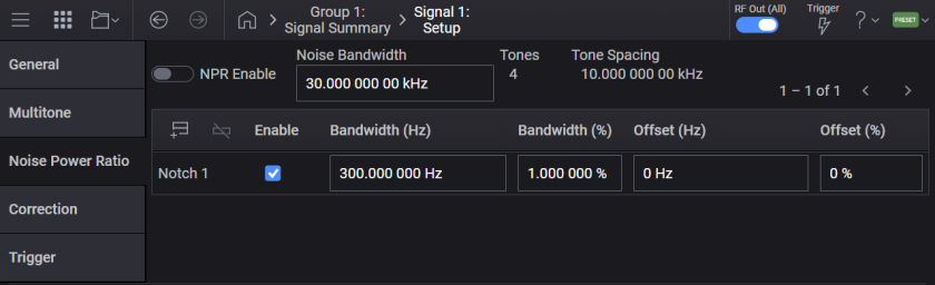
Noise Power Ratio (NPR) settings can be used to create notches (= to turn off the states of tones). When we have tones with tone spacing , Noise Bandwidth can be calculated with . At the -th notch, the relationship between Relative Width (%) and Absolute Width (Hz) is defined as and the relationship between Relative Center (%) and Absolute Center (Hz) is also defined as . At the -th tone, when is satisfied, the state of the tone is turned off.
The region includes the border line (see the 1st notch). Also, the border is not required to set the same frequency of the tone (see the 2nd notch).
Multiple notches can be overlapped (see the 3rd and the 4th notches).
Notch can be defined for out of the noise BW (see the 5th notch).
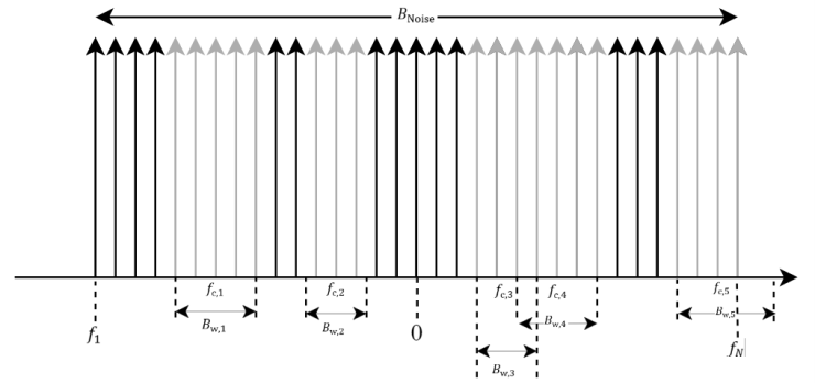
Turns NPR on or off. When on, notch parameters are applied to the waveform.
|
GUI Location |
Signals > Mode set to Multitone > Noise Power Ratio tab > NPR Enable |
|
SCPI Command |
[:SOURce]:GROup<group>:SIGNal<signal>:MTONe:ARB:NPR[:STATe] ON|OFF|1|0 [:SOURce]:GROup<group>:SIGNal<signal>:MTONe:ARB:NPR[:STATe]? |
|
SCPI Example |
:GRO:SIGN:MTON:ARB:NPR 1 :GRO:SIGN:MTON:ARB:NPR? |
|
Preset |
OFF |
|
State Saved |
Yes |
|
Initial S/W Revision |
A.14.00 |
Sets the noise bandwidth.
|
GUI Location |
Signals > Mode set to Multitone > Noise Power Ratio tab > Noise Bandwidth |
|
SCPI Command |
[:SOURce]:GROup<group>:SIGNal<signal>:MTONe:ARB:NPR:NBWidth <freq> [:SOURce]:GROup<group>:SIGNal<signal>:MTONe:ARB:NPR:NBWidth? |
|
SCPI Example |
:GRO:SIGN:MTON:ARB:NPR:NBW 60kHz :GRO:SIGN:MTON:ARB:NPR:NBW? |
|
Preset |
30 kHz |
|
Min |
(min(Tones) - 1) * Tone Spacing = Tone Spacing |
|
Max |
(max(Tones) - 1) * Tone Spacing = 200000 * Tone Spacing |
|
Resolution |
0.00001 Hz |
|
Couplings |
(Tones - 1) * Tone Spacing |
|
State Saved |
Yes |
|
Initial S/W Revision |
A.14.00 |
Returns Tones calculated from Noise Bandwidth. When NPR Enable is On, the value is synchronized with Tones in Multitone.
|
GUI Location |
Signals > Mode set to Multitone > Noise Power Ratio tab > Tones |
|
SCPI Command |
[:SOURce]:GROup<group>:SIGNal<signal>:MTONe:ARB:NPR:NTONes? |
|
SCPI Example |
:GRO:SIGN:MTON:ARB:NPR:NTON? |
|
Couplings |
Noise Bandwidth / Tone Spacing + 1 |
|
Initial S/W Revision |
A.14.00 |
Adds a notch.
|
GUI Location |
Signals > Mode set to Multitone > Noise Power Ratio tab > Add icon |
|
SCPI Command |
[:SOURce]:GROup<group>:SIGNal<signal>:MTONe:ARB:NPR:NOTCh:ADD |
|
SCPI Example |
:GRO:SIGN:MTON:ARB:NPR:NOTC:ADD |
|
Initial S/W Revision |
A.14.00 |
Deletes a notch.
|
GUI Location |
Signals > Mode set to Multitone > Noise Power Ratio tab > Delete icon |
|
SCPI Command |
[:SOURce]:GROup<group>:SIGNal<signal>:MTONe:ARB:NPR:NOTCh:DELete <number> |
|
SCPI Example |
:GRO:SIGN:MTON:ARB:NPR:NOTC:DEL 1 |
|
Initial S/W Revision |
A.14.00 |
Returns the number of notches. The maximum number of notches is 20.
|
GUI Location |
Signals > Mode set to Multitone > Noise Power Ratio tab > Count |
|
SCPI Command |
[:SOURce]:GROup<group>:SIGNal<signal>:MTONe:ARB:NPR:NOTCh:COUNt? |
|
SCPI Example |
:GRO:SIGN:MTON:ARB:NPR:NOTC:COUN? |
|
Initial S/W Revision |
A.14.00 |
Enables or disables the notch.
|
GUI Location |
Signals > Mode set to Multitone > Noise Power Ratio tab > Enable |
|
SCPI Command |
[:SOURce]:GROup<group>:SIGNal<signal>:MTONe:ARB:NPR:NOTCh<notch>[:STATe] [:SOURce]:GROup<group>:SIGNal<signal>:MTONe:ARB:NPR:NOTCh<notch>[:STATe]? |
|
SCPI Example |
:GRO:SIGN:MTON:ARB:NPR:NOTC ON :GRO:SIGN:MTON:ARB:NPR:NOTC? |
|
Preset |
ON |
|
State Saved |
Yes |
|
Initial S/W Revision |
A.14.00 |
Sets the notch bandwidth.
|
GUI Location |
Signals > Mode set to Multitone > Noise Power Ratio tab > Bandwidth (Hz) |
|
SCPI Command |
[:SOURce]:GROup<group>:SIGNal<signal>:MTONe:ARB:NPR:NOTCh<notch>:BANDwidth <freq> [:SOURce]:GROup<group>:SIGNal<signal>:MTONe:ARB:NPR:NOTCh<notch>:BANDwidth? |
|
SCPI Example |
:GRO:SIGN:MTON:ARB:NPR:NOTC:BAND 10 MHz :GRO:SIGN:MTON:ARB:NPR:NOTC:BAND? |
|
Preset |
300 Hz |
|
Min |
0 |
|
Max |
Noise Bandwidth * max(Relative Width) / 100 = 0.4 * Noise Bandwidth |
|
State Saved |
Yes |
|
Initial S/W Revision |
A.14.00 |
Sets the notch bandwidth percent.
|
GUI Location |
Signals > Mode set to Multitone > Noise Power Ratio tab > Bandwidth (%) |
|
SCPI Command |
[:SOURce]:GROup<group>:SIGNal<signal>:MTONe:ARB:NPR:NOTCh<notch>:BANDwidth:PERCent <real> [:SOURce]:GROup<group>:SIGNal<signal>:MTONe:ARB:NPR:NOTCh<notch>:BANDwidth:PERCent? |
|
SCPI Example |
:GRO:SIGN:MTON:ARB:NPR:NOTC:BAND:PERC 10 :GRO:SIGN:MTON:ARB:NPR:NOTC:BAND:PERC? |
|
Preset |
1 |
|
Min |
0 |
|
Max |
40 |
|
State Saved |
Yes |
|
Initial S/W Revision |
A.14.00 |
Sets the notch offset.
|
GUI Location |
Signals > Mode set to Multitone > Noise Power Ratio tab > Offset (Hz) |
|
SCPI Command |
[:SOURce]:GROup<group>:SIGNal<signal>:MTONe:ARB:NPR:NOTCh<notch>[:FREQuency]:OFFSet <freq> [:SOURce]:GROup<group>:SIGNal<signal>:MTONe:ARB:NPR:NOTCh<notch>[:FREQuency]:OFFSet? |
|
SCPI Example |
:GRO:SIGN:MTON:ARB:NPR:NOTC:FREQ:OFFS 1 MHz :GRO:SIGN:MTON:ARB:NPR:NOTC:FREQ:OFFS? |
|
Preset |
0 |
|
Min |
0 |
|
Max |
Noise Bandwidth * max(Relative Center) / 100 = 0.5 * Noise Bandwidth |
|
State Saved |
Yes |
|
Initial S/W Revision |
A.14.00 |
Sets the notch offset percent.
|
GUI Location |
Signals > Mode set to Multitone > Noise Power Ratio tab > Offset (%) |
|
SCPI Command |
[:SOURce]:GROup<group>:SIGNal<signal>:MTONe:ARB:NPR:NOTCh<notch>[:FREQuency]:OFFSet:PERCent <real> [:SOURce]:GROup<group>:SIGNal<signal>:MTONe:ARB:NPR:NOTCh<notch>[:FREQuency]:OFFSet:PERCent? |
|
SCPI Example |
:GRO:SIGN:MTON:ARB:NPR:NOTC:FREQ:OFFS:PERC 10 :GRO:SIGN:MTON:ARB:NPR:NOTC:FREQ:OFFS:PERC? |
|
Preset |
0 |
|
Min |
-50 |
|
Max |
50 |
|
State Saved |
Yes |
|
Initial S/W Revision |
A.14.00 |
Remote command only.
Query only. Returns values of all tones included in the internal tone table. Notch calculation according to Noise Power Ratio (NPR) settings is applied to this table. When NPR Enable is ON, a waveform is generated from the table.
|
SCPI Command |
[:SOURce]:GROup<group>:SIGNal<signal>:MTONe:ARB:NPR:SETup:TABLe? |
|
SCPI Example |
:GRO:SIGN:MTON:ARB:NPR:SET:TABL? |
| Notes | Query returns values in the order of state, frequency (Hz), power (dB), and phase (degree) for each tone in the table. For example, if the tone table includes 10 tones, 10 x 4 = 40 values are returned. |
|
State Saved |
No |
|
Initial S/W Revision |
A.14.00 |
N7621 Signal Studio for Multitone Distortion has a settings file (.mtd file). Import elements; Tone Count, Tone Spacing, Noise Offset, Phase Distribution, Phase Seed, Notch Center, Notch Width, Number of Iterations, and Desired Suppression under the NPR element. The value of Noise Offset is imported to the frequency offset and deducted from the RF Frequency. The negative value of Desired Suppression is imported to the tolerance.
|
SCPI Command |
[:SOURce]:GROup<group>:SIGNal<signal>:MTONe:ARB:NPR:MTD:FILE:IMPort <"file path"> |
|
SCPI Example |
:GRO:SIGN:MTON:ARB:NPR:MTD:FILE:IMPort "a.mtd" |
|
Initial S/W Revision |
A.14.00 |
Multitone Correction eliminates inter-modulation distortion (IMD) on notches.
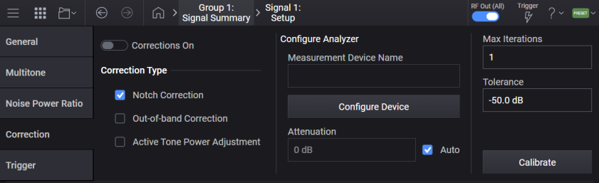
Turns the correction on or off. The setting cannot be turned on before calibration. N7621APPC with subscription date December 1, 2023 is required to turn it on.
|
GUI Location |
Signals > Mode set to Multitone > Calibration > Corrections On |
|
SCPI Command |
[:SOURce]:GROup<group>:SIGNal<signal>:MTONe:ARB:CORRection[:STATe] ON|OFF|1|0 [:SOURce]:GROup<group>:SIGNal<signal>:MTONe:ARB:CORRection[:STATe]? |
|
SCPI Example |
:GRO:SIGN:MTON:ARB:CORR 1 :GRO:SIGN:MTON:ARB:CORR? |
|
Preset |
OFF |
|
State Saved |
Yes |
|
Initial S/W Revision |
A.14.00 |
Turns the notch correction off or on. When on, tones whose states are off in the tone table are corrected to reduce IMD.
|
GUI Location |
Signals > Mode set to Multitone > Calibration > Notch Correction |
|
SCPI Command |
[:SOURce]:GROup<group>:SIGNal<signal>:MTONe:ARB:CORRection:NOTCh[:STATe] ON|OFF|1|0 [:SOURce]:GROup<group>:SIGNal<signal>:MTONe:ARB:CORRection:NOTCh[:STATe]? |
|
SCPI Example |
:GRO:SIGN:MTON:ARB:CORR:NOTC 1 :GRO:SIGN:MTON:ARB:CORR:NOTC? |
|
Preset |
ON |
|
State Saved |
Yes |
|
Initial S/W Revision |
A.14.00 |
Turns the out-of-band correction off or on. When on, tones in the adjacent channels of the tone table are corrected to reduce IMD. This correction employs approximately three times of Noise Bandwidth.
|
GUI Location |
Signals > Mode set to Multitone > Calibration > Out-of-band Correction |
|
SCPI Command |
[:SOURce]:GROup<group>:SIGNal<signal>:MTONe:ARB:CORRection:OOBand[:STATe] ON|OFF|1|0 [:SOURce]:GROup<group>:SIGNal<signal>:MTONe:ARB: CORRection:OOBand[:STATe]? |
|
SCPI Example |
:GRO:SIGN:MTON:ARB:CORR:OOB 1 :GRO:SIGN:MTON:ARB:CORR:OOB? |
|
Preset |
OFF |
|
State Saved |
Yes |
|
Initial S/W Revision |
A.14.00 |
Turns the active tone power adjustment off or on. When on, tones whose states are on in the multitone table are corrected to adjust the relative amplitude defined in the multitone table.
|
GUI Location |
Signals > Mode set to Multitone > Calibration > Active Tone Power Adjustment |
|
SCPI Command |
[:SOURce]:GROup<group>:SIGNal<signal>:MTONe:ARB:CORRection:ATPower[:STATe] ON|OFF|1|0 [:SOURce]:GROup<group>:SIGNal<signal>:MTONe:ARB: CORRection:ATPower[:STATe]? |
|
SCPI Example |
:GRO:SIGN:MTON:ARB:CORR:ATP 1 :GRO:SIGN:MTON:ARB:CORR:ATP? |
|
Preset |
OFF |
|
State Saved |
Yes |
|
Initial S/W Revision |
A.14.00 |
Sets the device.
|
GUI Location |
Signals > Mode set to Multitone > Calibration > Measurement Device Name |
|
SCPI Command |
:SYSTem:COMMunicate:MTONe:ARB:CORRection:DEVice <"device name"> :SYSTem:COMMunicate:MTONe:ARB:CORRection:DEVice? |
|
SCPI Example |
:SYST:COMM:MTON:ARB:CORR:DEV "InstSA" :SYST:COMM:MTON:ARB:CORR:DEV? |
|
State Saved |
Yes |
|
Initial S/W Revision |
A.14.00 |
Sets the attenuation. When the Attenuation Auto is on, the value is set to the receiver attenuation.
|
GUI Location |
Signals > Mode set to Multitone > Calibration > Attenuation |
|
SCPI Command |
[:SOURce]:GROup{1:16}:SIGNal{1:8}:MTONe:ARB:CORRection:RECeiver:ATTenuation <rel_ampl> [:SOURce]:GROup{1:16}:SIGNal{1:8}:MTONe:ARB:CORRection:RECeiver:ATTenuation? |
|
SCPI Example |
:GRO:SIGN:MTON:ARB:NPR:CORR:REC:ATT 20 dB :GRO:SIGN:MTON:ARB:NPR:CORR:REC:ATT? |
|
Preset |
0 |
|
State Saved |
Yes |
|
Initial S/W Revision |
A.14.00 |
Turns the receiver attenuation auto off or on. When on, the receiver attenuation is automatically adjusted. Otherwise, the value of the Attenuation is used for the receiver attenuation. When the attenuation is changed, this value is turned off.
|
GUI Location |
Signals > Mode set to Multitone > Calibration > Attenuation Auto |
|
SCPI Command |
[:SOURce]:GROup<group>:SIGNal<signal>:MTONe:ARB:CORRection:RECeiver:ATTenuation:AUTO ON|OFF|1|0 [:SOURce]:GROup<group>:SIGNal<signal>:MTONe:ARB:CORRection:RECeiver:ATTenuation:AUTO? |
|
SCPI Example |
:GRO:SIGN:MTON:ARB:CORR:REC:ATT 1 :GRO:SIGN:MTON:ARB:CORR:REC:ATT? |
|
Preset |
ON |
|
State Saved |
Yes |
|
Initial S/W Revision |
A.14.00 |
Sets the iterations. Calibration is repeated until the iterations until the notch depth after calibration is larger than the tolerance. The calibration time is increased in proportion to 2^(n+1) at the n-th iteration.
|
GUI Location |
Signals > Mode set to Multitone > Calibration > Max Iterations |
|
SCPI Command |
[:SOURce]:GROup<group>:SIGNal<signal>:MTONe:ARB:CORRection:ITERations <integer> [:SOURce]:GROup<group>:SIGNal<signal>:MTONe:ARB:SETup:CORRection:ITERations? |
|
SCPI Example |
:GRO:SIGN:MTON:ARB:CORR:ITER 5 :GRO:SIGN:MTON:ARB:CORR:ITER? |
|
Preset |
1 |
|
Min |
1 |
|
Max |
10 |
|
State Saved |
Yes |
|
Initial S/W Revision |
A.14.00 |
Sets the tolerance. Calibration is repeated until the iterations when the notch depth after calibration is larger than the tolerance.
|
GUI Location |
Signals > Mode set to Multitone > Calibration > Tolerance |
|
SCPI Command |
[:SOURce]:GROup<group>:SIGNal<signal>:MTONe:ARB:CORRection:TOLerance <rel_ampl> [:SOURce]:GROup<group>:SIGNal<signal>:MTONe:ARB:CORRection:TOLerance? |
|
SCPI Example |
:GRO:SIGN:MTON:ARB:CORR:TOL -60 dB :GRO:SIGN:MTON:ARB:CORR:TOL? |
|
Preset |
-50 dB |
|
Min |
-100 |
|
Max |
-40 |
|
Resolution |
0.1 dB |
|
State Saved |
Yes |
|
Initial S/W Revision |
A.14.00 |
Calibrates a multitone waveform. When the multitone waveform is successfully calibrated, Enable is automatically turned on.
|
GUI Location |
Signals > Mode set to Multitone > Calibration > Calibrate |
|
SCPI Command |
[:SOURce]:GROup<group>:SIGNal<signal>:MTONe:ARB:CORRection:CALbrate |
|
SCPI Example |
:GRO:SIGN:MTON:ARB:CORR:CAL |
|
Initial S/W Revision |
A.14.00 |
Aborts the multitone calibration.
|
GUI Location |
Signals > Mode set to Multitone > Calibration > Calibrate > Abort |
|
SCPI Command |
[:SOURce]:GROup<group>:SIGNal<signal>:MTONe:ARB:CORRection:CALibrate:ABORt |
|
SCPI Example |
:GRO:SIGN:MTON:ARB:CORR:CAL:ABOR |
|
Initial S/W Revision |
A.14.00 |
Remote command only.
Query only. Returns values of all tones included in the internal tone table. Calibration results are applied to this table. When Correction is on, a waveform is generated from the table.
|
SCPI Command |
[:SOURce]:GROup<group>:SIGNal<signal>:MTONe:ARB:CORRection:SETup:TABLe? |
|
SCPI Example |
:GRO:SIGN:MTON:ARB:CORR:SET:TABL? |
| Notes | Query returns values in the order of state, frequency (Hz), power (dB), and phase (degree) for each tone in the table. For example, if the tone table includes 10 tones, then 10 x 4 = 40 values are returned. |
|
State Saved |
No |
|
Initial S/W Revision |
A.14.00 |
Remote command only.
Modifies the indicated tone (row) of the multitone waveform. The details of the parameters are as follows:
<row_number>: The row number of the table output by the TABLe command. If <row_number> exceeds the size of table, an error -222 message "Data out of range; Selected row does not exist." is raised.
<power>: The power level of the tone defined in the row number, in decibels (dB). Power levels for all tones share the total power of the channel with the specified ratios. For each tone, the minimum is -200 dB and the maximum is 30 dB.
<phase>: The phase, in degrees, of the tone relative to the carrier.
<state>: The state of the tone in this row can be enabled (1) or disabled (0).
|
SCPI Command |
[:SOURce]:GROup<group>:SIGNal<signal>:MTONe:ARB:SETup:TABLe:ROW <row_number>,<power>,<phase>,<state> [:SOURce]:GROup<group>:SIGNal<signal>:MTONe:ARB:SETup:TABLe:ROW? <row_number> |
|
SCPI Example |
:GRO:SIGN:MTON:ARB:SET:TABL:ROW 1,0.0,0.0,1 :GRO:SIGN:MTON:ARB:SET:TABL:ROW? 5 |
| Notes | Query returns values in the order of state, frequency (Hz), relative amplitude (dB), and phase (degree) for the specified row in the tone table. For example, if the tone table includes 10 tones, then 10 x 4 = 40 values are returned. |
| Backwards Compatibility SCPI |
[:SOURce]:RADio:MTONe:ARB:SETup:TABLe:ROW <row_number>,<power>,<phase>,<state> to [:SOURce]:GROup1:SIGNal1:MTONe:ARB:SETup:TABLe:ROW <row_number>,<power>,<phase>,<state> [:SOURce]:RADio:MTONe:ARB:SETup:TABLe:ROW? to [:SOURce]:GROup1:SIGNal1:MTONe:ARB:SETup:TABLe:ROW? |
| Backwards Compatibility Notes | [:SOURce]:RADio:MTONe:ARB:SETup:TABLe:ROW? query returns values in a different order from the current command. Query returns values in the order of frequency (Hz), relative amplitude (dB), phase (degree), and state for the specified row in the tone table. |
|
Initial S/W Revision |
A.18.00 |
Single Tone generates a single CW tone at a specified offset to the channel’s RF Frequency. This capability requires license model N7621APPC.
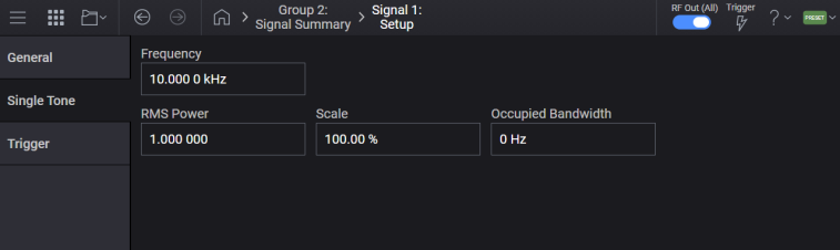
Sets the frequency of a single CW tone with respect to the channel’s RF Frequency.
|
GUI Location |
Signals > Mode set to Single Tone > Single Tone tab > Frequency Offset |
|
SCPI Command |
[:SOURce]:GROup<group>:SIGNal<signal>:SSB:FREQuency <freq> [:SOURce]:GROup<group>:SIGNal<signal>:SSB:FREQuency? |
|
SCPI Example |
GRO:SIGN:SSB:FREQ 10.5 kHz GRO:SIGN:SSB:FREQ? |
|
Preset |
10 kHz |
|
State Saved |
Yes |
|
Min |
-(Bandwidth/2) For bandwidth, see Vector Modulation Bandwidth Limitations. |
|
Max |
Bandwidth/2 For bandwidth, see Vector Modulation Bandwidth Limitations. |
|
Backwards Compatibility SCPI |
The following commands are not recommended. They are for the convenience of users with existing remote programs developed for earlier versions of the signal generator or ported from a similar product. Alias [:SOURce]:SIGNal[1]:SSB:FREQuency to :SOURce:GROup1:SIGNal1:SSB:FREQuency Alias [:SOURce]:SIGNal2:SSB:FREQuency to :SOURce:GROup2:SIGNal1:SSB:FREQuency |
|
Initial S/W Revision |
A.01.00 |
|
Modified S/W Revision |
A.09.00 Added :GROup keyword |
Sets the RMS of Single Tone signal.
When a single tone signal is generated (or recalculated), this value is set based on the generated signal.
|
GUI Location |
Signals > Mode set to Single Tone > Single Tone tab > RMS Power |
|
SCPI Command |
[:SOURce]:GROup<group>:SIGNal<signal>:SSB:RMS <real> [:SOURce]:GROup<group>:SIGNal<signal>:SSB:RMS? |
|
SCPI Example |
GRO:SIGN:SSB:RMS 1 GRO:SIGN:SSB:RMS? |
|
Preset |
1 |
|
State Saved |
Yes |
|
Min |
0.1 |
|
Max |
1.414213562 |
|
Resolution |
0.000000001 |
|
Initial S/W Revision |
A.15.00 |
Sets the scale factor of Single Tone signal.
When a single tone signal is generated (or recalculated), this value is set based on the generated signal.
|
GUI Location |
Signals > Mode set to Single Tone > Single Tone tab > Scale |
|
SCPI Command |
[:SOURce]:GROup<group>:SIGNal<signal>:SSB:SCALe <real> [:SOURce]:GROup<group>:SIGNal<signal>:SSB:SCALe? |
|
SCPI Example |
GRO:SIGN:SSB:SCAL 100 GRO:SIGN:SSB:SCAL? |
|
Preset |
100 For M9484C: 70 |
|
State Saved |
Yes |
|
Min |
1 |
|
Max |
100 |
|
Resolution |
0.01 |
|
Initial S/W Revision |
A.15.00 |
| Modified S/W Version | A.16.00 - Changed Preset from 100 to 70 for M9484C |
Sets the occupied bandwidth of Single Tone signal.
When a single tone signal is generated (or recalculated), this value is set to the same value as 2 x Single Tone Frequency (abs value).
|
GUI Location |
Signals > Mode set to Single Tone > Single Tone tab > Occupied Bandwidth |
|
SCPI Command |
[:SOURce]:GROup<group>:SIGNal<signal>:SSB:OBWidth <freq> [:SOURce]:GROup<group>:SIGNal<signal>:SSB:OBWidth? |
|
SCPI Example |
GRO:SIGN:SSB:OBW 140 kHz GRO:SIGN:SSB:OBW? |
|
Preset |
0 |
|
State Saved |
Yes |
|
Min |
0 Hz |
|
Max |
BW For BW, see Vector Modulation Bandwidth Limitations table. |
|
Resolution |
1 Hz |
|
Initial S/W Revision |
A.15.00 |
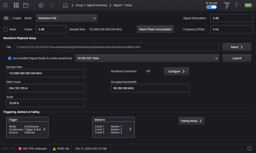
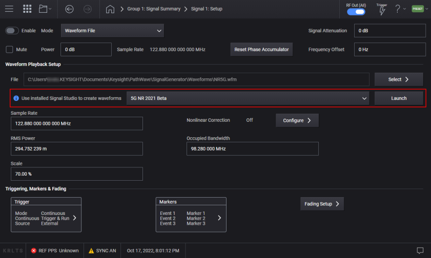
Launches the selected Signal Studio application. All available Signal Studio applications are listed for the instrument.
Signal Studio applications, such as Custom Modulation (N7608C) support auto configuration. If Signal Studio supports auto configuration, it is automatically connected to the specified Signal of localhost VXG when launched from this control. For example, when it’s launched from the Signal block of Ch2, it is connected to Ch2. For Signal Studio applications that do not support auto configuration the VXG is not automatically connected and must be done manually.
For 2-channel instruments:
If the selected Signal Studio application is already running on one of the channels, the existing Signal Studio is used instead of starting a new instance.
If the instance of Signal Studio is already running on a channel (for example, channel 1), and you wish to use the other channel (channel 2), close the existing instance and relaunch a new instance from the other channel (channel 2).
|
GUI Location |
Signals > Signal Studio > Launch |
|
Notes |
There is no equivalent SCPI command, this is a GUI function only. |
|
Initial S/W Revision |
A.02.00 |
|
Modified S/W Revision |
A.11.50 - Updated for M9484C |
Allows you to select waveform data to play. Both waveform data in ARB memory and non-volatile memory can be selected.
If you have Option 8SG, waveform files assigned to the same signal group must have unique file names. The ARB waveform memory references the file name alone and does not distinguish between different directories. For more information, refer to ARB Waveform Memory.
When waveform data in non-volatile memory is selected, it first uploads the data to the Arb memory and the uploaded data is played. The data in non-volatile memory can be specified either with a path to the file or MSUS for non-volatile waveform data. i.e. "SNVWFM" and "NVWFM."
Waveform on the Arb memory can be selected either with "SWFMn" or "WFMn." See also ARB Waveform Memory.
Even when the file with the same name on the non-volatile memory is selected, the waveform is uploaded to the arb memory.
When a filename that does not exist is given to this command, the value is not updated and -257, "File name error" is issued. Setting an empty string, e.g. GRO:SIGN:WAV "", ends up with the same result. The value isn’t changed, and the error is issued.
File names and file paths must comprise ASCII characters only. Otherwise, a "File name not found" error occurs. In addition, a file name cannot contain a comma or a semicolon.
|
GUI Location |
Signals > Mode set to Waveform File > Waveform File tab > File |
|
SCPI Command |
[:SOURce]:GROup<group>:SIGNal<signal>:WAVeform[:SELect] <string> [:SOURce]:GROup<group>:SIGNal<signal>:WAVeform[:SELect]? |
|
SCPI Example |
GRO:SIGN:WAV "wav1.wfm" GRO:SIGN:WAV? |
|
Preset |
"" |
|
State Saved |
Yes |
|
Backwards Compatibility SCPI |
The following commands are not recommended. They are for the convenience of users with existing remote programs developed for earlier versions of the signal generator or ported from a similar product. Alias [:SOURce]:SIGNal[1]:WAVeform[:SELect] to :SOURce:GROup1:SIGNal1:WAVeform[:SELect] Alias [:SOURce]:SIGNal2:WAVeform[:SELect] to :SOURce:GROup2:SIGNal1:WAVeform[:SELect] |
|
Initial S/W Revision |
A.01.00 |
|
Modified S/W Revision |
A.09.00 Added :GROup keyword |
If you use an embedded application (e.g. 5G NR, Custom Modulation) to configure and generate a waveform, clicking Generate automatically saves the waveform configuration as a metadata file along with the generated waveform file. Then whenever the waveform is selected from the Signal Setup screen, the Edit in App button appears next to the File field, providing easy access to the appropriate application with the configuration used to generate this waveform.
|
Format |
File Extension |
Description |
|---|---|---|
|
Signal Studio |
*.wfm |
Waveforms exported from Keysight Signal Studio applications. |
|
Keysight 16-bit binary |
*.wiq *.bin *.WAVEFORM |
Contains interleaved I/Q samples (I0, Q0, I1, Q1, …). Values must be stored in 16-bit signed integers. The Default Binary File Format can be set to either Big Endian or Little Endian. See Keysight 16-Bit Binary in the Creating and Downloading Waveforms tutorial. |
|
ASCII |
*.csv *.txt |
Two floating-point numbers (one for I and the other for Q) delimited by a comma, a tab or a whitespace, should appear in each line. Each line can have more than two values, but only the first two values are read as IQ point data. For example, the csv file may have values for I, Q, Marker1, Marker2, Marker3, and Marker4 in one line. In this case, only the first two values in the line are imported as an IQ point. The rest of the values are discarded. Only UTF-8 encoding with and without BOM is supported. If the max abs value of I or Q is less than or equal to 1.0, no scaling is applied to the IQ data. If it is more than 1.0, the IQ data is normalized with the max abs value of I or Q. |
|
Sequence |
*.seq |
Created by Keysight signal generators. |
|
MATLAB |
*.mat |
The MAT file format (version 4, 6, 7, and 7.3) and the HDF5 format are supported. See MATLAB in the Creating and Downloading Waveforms tutorial. |
The waveform header contains waveform properties such as the sample rate and the RMS value.
A secure waveform file (*.wfm) and a sequence file (*.seq) each contain a header. Other files don’t contain a header but an external header file is supported. An external header file must have the same name as the waveform file with an extension of .whd or .HEADER. It must be placed in the same folder as the associated waveform file.
When a waveform file is selected, the following settings are updated:
Sample Rate if specified in the header.
Scale if specified in the header.
RMS
If a value is specified in the header, it is updated to that value. Otherwise,
If a secure waveform file is selected, it is set to 1.0.
If a sequence file is selected and all the waveforms referenced in the header have been uploaded, it is calculated from the RMS value and the length of the waveforms.
If a non-secure waveform file is selected, it’s calculated from the waveform.
Occupied Bandwidth
If a value is specified in the header, it is updated to that value.
If a value is not specified but the Sample Rate is specified in the header, it is updated to that Sample Rate.
Manually updating the Waveform File Occupied Bandwidth GUI value does not adjust the occupied bandwidth of the waveform. Rather, it sets the frequency span over which the RF flatness correction and dynamic range optimizations occur. See Optimize Dynamic Range with OBW for more information.
ALC Hold Marker Routing if specified in the header.
RF Blanking Marker Routing if specified in the header.
This command takes the current settings for the selected waveform file and saves them to the header file for the waveform. A waveform file must be selected for this command to function. The settings saved in the header are:
Occupied Bandwidth
RMS Power
Sample Rate
Scale
|
SCPI Command |
[:SOURce]:GROup<group>:SIGNal<signal>:WAVeform:HEADer:SAVE |
|
SCPI Example |
:GRO:SIGN:WAV:HEAD:SAVE |
|
Notes |
Attempting to send this command when the selected waveform is a .wfm file, raises the error +629,"File format invalid; <filename> has an extension that does not support saving waveform headers." The file formats that support Header Save are:
|
|
Backwards Compatible SCPI |
N51xxB: [:SOURce]:RADio:ARB:HEADer:SAVE |
| Backwards Compatible Notes |
For N51xxB: Alias [:SOURce]:RADio:ARB:HEADer:SAVE to :GROup1:SIGNal1:WAVeform:HEADer:SAVE |
|
Initial S/W Revision |
A.14.00 |
| Modified S/W Revision | A.17.00 - Added support for Sequence (.seq) files |
The following table shows MSUS examples.
|
SCPI command example |
File |
|---|---|
|
GRO:SIGN:WAV "SNVWFM:abc" |
<Documents>\Keysight\PathWave\SignalGenerator\Waveforms\abc.wfm |
|
GRO:SIGN:WAV "NVWFM:abc" |
<Documents>\Keysight\PathWave\SignalGenerator\Waveforms\abc.wiq |
|
GRO:SIGN:WAV "SWFM1:abc" |
Waveform "abc" in Ch1 ARB memory |
|
GRO:SIGN:WAV "WFM1:abc" |
Waveform "abc" in Ch1 ARB memory |
|
GRO:SIGN:WAV "SWFM2:abc" |
Waveform "abc" in Ch2 ARB memory |
Please note that there is no MSUS for .bin extension. To select a .bin file, relative or absolute path can be used as shown below.
GRO:SIGN:WAV "abc.bin"
Auto folder selection works for this setting in the same way as memory commands, defined in the ARB Waveform Memory topic. See also File Location and Default Folders in that same topic for details.
With Auto Folder Selection, the folder of waveform file on non-volatile memory is automatically selected by the extension of file name when relative file path is given as command parameter. For example, when
GRO:SIGN:WAV "abc.wfm"
is sent, the software looks at <Documents>\Keysight\PathWave\SignalGenerator\Waveforms\ folder as a location of waveform file.
If the extension is not supported by Auto Folder Selection, the file path is determined based on the default folder, <Documents>\Keysight\PathWave\SignalGenerator.
The following table shows some of waveform file path examples and which folders are selected.
|
SCPI command example |
Folder |
|---|---|
|
GRO:SIGN:WAV "abc.wfm" |
<Documents>\Keysight\PathWave\SignalGenerator\Waveforms\ |
|
GRO:SIGN:WAV "myDir\abc.wfm" |
<Documents>\Keysight\PathWave\SignalGenerator\Waveforms\myDir |
|
GRO:SIGN:WAV "C:\wfm\abc.wfm" |
C:\wfm\ |
|
GRO:SIGN:WAV "abc.wiq" |
<Documents>\Keysight\PathWave\SignalGenerator\Waveforms\ |
|
GRO:SIGN:WAV "abc.bin" |
<Documents>\Keysight\PathWave\SignalGenerator\ |
|
GRO:SIGN:WAV "abc.csv" |
<Documents>\Keysight\PathWave\SignalGenerator\ |
|
GRO:SIGN:WAV "Waveforms\abc.bin" |
<Documents>\Keysight\PathWave\SignalGenerator\Waveforms\ |
If an inappropriate file extension is used, a non-intuitive folder is selected. The following table shows such examples.
|
SCPI command example |
Folder |
|---|---|
|
GRO:SIGN:WAV "abc.sgen" |
<Documents>\Keysight\PathWave\SignalGenerator\States\ |
|
GRO:SIGN:WAV "..\abc.sgen" |
<Documents>\Keysight\PathWave\SignalGenerator |
An .sgen file is usually a state file, in which instrument settings are saved, however, it is possible to create a signal file with .sgen and then select it as a waveform file. For example, you can send your waveform file with
:MMEM:DATA "abc.sgen", …
and select it with
:GRO:SIGN:WAV "abc.sgen"
This works perfectly, however, the file is saved in the "States" folder under the default folder because Auto Folder Detection designates the "States" folder as the location for .sgen files.
If the number of samples in the specified waveform file is smaller than the Segment Length Minimum or is not a multiple of the Waveform Quantum, the VXG can automatically extend it by either repeating the waveform or appending zeros at the end. The extension method can be configured by the Waveform Extension Method. A message is shown if extension occurs.
Waveform files can be of type .wfm, .csv, .txt, .wiq, .bin, .mat, .hdf, .h5, or .bnd. See Supported File Formats below. The file must exist on the instrument’s disk or a mapped network drive (NV or SNV memory); the file cannot be in the instruments volatile memory (SWFM).
Waveforms must be a minimum of 1024 samples.
Use the File Select button to navigate to the file browser.

Within the ![]() file browser, select the desired waveform file.
file browser, select the desired waveform file.
Attempting to use an inappropriate waveform file will result in an error when the file is actually used, not necessarily when the waveform file is selected via the Select button.
File names and file paths must comprise ASCII characters only. Otherwise, a "File name not found" error occurs. In addition, a file name cannot contain a comma or a semicolon.
|
Format |
File Extension |
Description |
|---|---|---|
|
Signal Studio |
*.wfm |
Waveforms exported from Keysight Signal Studio applications. |
|
Keysight 16-bit binary |
*.wiq *.bin *.WAVEFORM |
Contains interleaved I/Q samples (I0, Q0, I1, Q1, …). Values must be stored in 16-bit signed integers. The Default Binary File Format can be set to either Big Endian or Little Endian. See Keysight 16-Bit Binary in the Creating and Downloading Waveforms tutorial. |
|
ASCII |
*.csv *.txt |
Two floating-point numbers (one for I and the other for Q) delimited by a comma, a tab or a whitespace, should appear in each line. Each line can have more than two values, but only the first two values are read as IQ point data. For example, the csv file may have values for I, Q, Marker1, Marker2, Marker3, and Marker4 in one line. In this case, only the first two values in the line are imported as an IQ point. The rest of the values are discarded. Only UTF-8 encoding with and without BOM is supported. If the max abs value of I or Q is less than or equal to 1.0, no scaling is applied to the IQ data. If it is more than 1.0, the IQ data is normalized with the max abs value of I or Q. |
|
Sequence |
*.seq |
Created by Keysight signal generators. |
|
MATLAB |
*.mat |
The MAT file format (version 4, 6, 7, and 7.3) and the HDF5 format are supported. See MATLAB in the Creating and Downloading Waveforms tutorial. |
|
GUI Location |
System Menu > Configure Channels >2 Channel Bonded or 4 Channel Bonded > Signals > File |
|
SCPI Command |
[:SOURce]:GROup<group>:CBONded:WAVeform[:SELect] <string> [:SOURce]:GROup<group>:CBONded:WAVeform[:SELect]? |
|
SCPI Example |
GRO:CBON:WAV "wav1.wfm" GRO:CBON:WAV? |
|
Couplings |
If the selected waveform file is not bonded (*.bnd), bonded vector modulation cannot be set to ON. Likewise, if you select a non-bonded waveform file (e.g. *.wfm) while bonded vector modulation is on, it will be turned OFF. |
|
Preset |
"" |
|
State Saved |
Yes |
|
SCPI Change |
[:SOURce]:CBONded<bondingset>:WAVeform[:SELect] <string> has been changed to [:SOURce]:GROup<group>:CBONded:WAVeform[:SELect] <string>. Prior use of :SOUR:CBON:WAV or :SOUR:CBON1:WAV is now :SOUR:GRO1:CBON:WAV. |
|
Initial S/W Revision |
A.07.00 |
|
Modified S/W Revision |
A.10.00 Changed SCPI: Added :GROup<group> and removed <bondingset> from :CBONded |
Allows you to configure and set the nonlinear correction for the signal. By default, it is set to Off.
When you select a waveform file, the Configure button is enabled that allows you to configure the nonlinear correction.

The instrument provides the following type
| Correction Type | Description | Availability |
|
Real-Time Instrument Nonlinear Correction |
Compensates for the instrument’s nonlinearity without measuring correction For details, refer to Real-Time Instrument Nonlinear Correction. |
M9484C with Option NLC |
| Instrument Nonlinear Correction |
Compensates the instrument’s nonlinearity For details, refer to Instrument Nonlinear Correction. |
M9484C with N7653APPC subscription date of 2020.1215 or later |
| DUT Nonlinear Correction |
Used by X-Apps Power Amplifier Test. X-Apps extract correction coefficients, which are applied before waveform upload. For details, refer to DUT Nonlinear Correction. |
Keysight N9055EM0E Power Amplifier Test X-Apps |
When Nonlinear Correction is enabled, an icon appears in the Signal Block, as shown below.
R indicates Real-Time Instrument nonlinear correction.
D indicates DUT nonlinear correction.
I indicates instrument nonlinear correction.
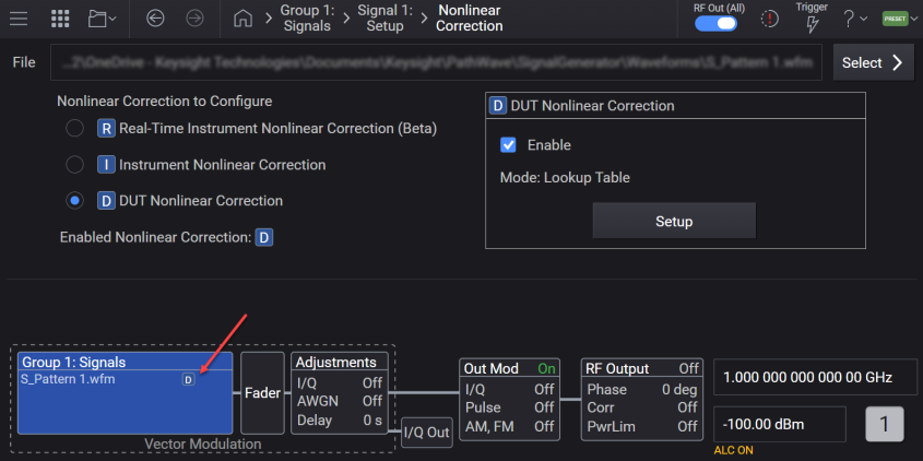
Sets the sample rate of the modulating waveform, accepts frequency units (e.g., 100 MHz).
|
GUI Location |
Signals > Mode set to Waveform File >Mode set to Waveform File > Waveform File tab > Sample Rate |
|
SCPI Command |
[:SOURce]:GROup<group>:SIGNal<signal>:WAVeform:SCLock:RATE <freq> [:SOURce]:GROup<group>:SIGNal<signal>:WAVeform:SCLock:RATE? |
|
SCPI Example |
GRO:SIGN:WAV:SCL:RATE 100 MHz GRO:SIGN:WAV:SCL:RATE? |
| Preset |
For Sample Rate, see Vector Modulation Bandwidth Limitations table. |
|
State Saved |
Yes |
|
Min |
M9484C: 100 Hz |
| Max |
For Sample Rate, see Vector Modulation Bandwidth Limitations table. |
|
Resolution |
0.000001 Hz |
|
Backwards Compatibility SCPI |
The following commands are not recommended. They are for the convenience of users with existing remote programs developed for earlier versions of the signal generator or ported from a similar product. Alias [:SOURce]:SIGNal[1]:WAVeform:SCLock:RATE to :SOURce:GROup1:SIGNal1:WAVeform:SCLock:RATE Alias [:SOURce]:SIGNal2:WAVeform:SCLock:RATE to :SOURce:GROup2:SIGNal1:WAVeform:SCLock:RATE |
|
Initial S/W Revision |
A.01.00 |
|
Modified S/W Revision |
A.09.00 Added :GROup keyword |
Sets the sample rate of the bonded modulating waveform, accepts frequency units (e.g., 3.8 GHz).
The value is not editable in a GUI when a Bonded Waveform File is selected
|
GUI Location |
System Menu > Configure Channels > Bonded > Signals > Sample Rate |
|
SCPI Command |
[:SOURce]:GROup<group>:CBONded:WAVeform:SCLock:RATE <freq> [:SOURce]:GROup<group>:CBONded:WAVeform:SCLock:RATE? |
|
SCPI Example |
GRO:CBON:WAV:SCL:RATE 4 GHZ GRO:CBON:WAV:SCL:RATE? |
|
Preset |
For M9484C: Option R25
|
|
State Saved |
Yes |
|
Min |
2.0 Hz |
|
Max |
For M9484C: Option R25 = 6.0 GHz
|
|
Resolution |
0.000001 Hz |
|
SCPI Change |
[:SOURce]:CBONded<bondingset>:WAVeform:SCLock:RATE <freq> has been changed to [:SOURce]:GROup<group>:CBONded:WAVeform:SCLock:RATE <freq>. Prior use of :SOUR:CBON:WAV:SCL:RATE or :SOUR:CBON1:WAV:SCL:RATE is now :SOUR:GRO1:CBON:WAV:SCL:RATE. |
|
Initial S/W Revision |
A.07.00 |
|
Modified S/W Revision |
A.10.00 - Changed SCPI: Added :GROup<group> and removed <bondingset> from :CBONded A.15.00 - Changed Max values for 4 Channel Bonded |
Sets the RMS on the modulating waveform.
GUI Location | Signals > Mode set to Waveform File > Waveform File tab > RMS Power |
SCPI Command | [:SOURce]:GROup<group>:SIGNal<signal>:WAVeform:RMS <real> [:SOURce]:GROup<group>:SIGNal<signal>:WAVeform:RMS? |
SCPI Example | GRO:SIGN:WAV:RMS 1 GRO:SIGN:WAV:RMS? |
Preset | 1 |
State Saved | Yes |
Min | 0.1 |
Max | 1.414213562 |
Resolution | 0.000000001 |
Initial S/W Revision | A.01.00 |
Backwards Compatibility SCPI | The following commands are not recommended. They are for the convenience of users with existing remote programs developed for earlier versions of the signal generator or ported from a similar product. Alias [:SOURce]:SIGNal[1]:WAVeform:RMS to :SOURce:GROup1:SIGNal1:WAVeform:RMS Alias [:SOURce]:SIGNal2:WAVeform:RMS to :SOURce:GROup2:SIGNal1:WAVeform:RMS |
Initial S/W Revision | A.01.00 |
Modified S/W Revision | A.03.00 A.09.00 Added :GROup keyword |
GUI option only.
This button calculates the RMS Power from the selected waveform header file and displays this value in the RMS Power field.
GUI Location | Signals > Mode set to Waveform File > Waveform File tab > Calculate |
Initial S/W Revision | A.17.00 |
Click the  button displayed with the RMS Power field to access the Calculate button.
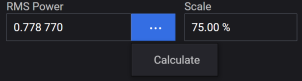
Sets the RMS of the bonded modulating waveform.
On selection of a file, the RMS setting is automatically updated as follows:
If a .wfm or .bnd file is selected, the value from the file is used.
If a different type of file is selected, a value is calculated from I/Q samples. Consecutive zero samples are ignored following the MXG implementation. See the following figure.

You can override the calculated RMS value, however be aware that loading another file, recalling an instrument state, or performing a Preset will change the setting.
The value is not editable in a GUI when a Bonded Waveform File is selected.
GUI Location | System Menu > Configure Channels > Bonded > Signals > RMS Power |
SCPI Command | [:SOURce]:GROup<group>:CBONded:WAVeform:RMS [:SOURce]:GROup<group>:CBONded:WAVeform:RMS? |
SCPI Example | GRO:CBON:WAV:RMS 1 GRO:CBON:WAV:RMS? |
Preset | 1 |
State Saved | Yes |
Min | 0.1 |
Max | 1.414213562 |
Resolution | 0.000000001 |
SCPI Change | [:SOURce]:CBONded<bondingset>:WAVeform:RMS <real> has been changed to [:SOURce]:GROup<group>:CBONded:WAVeform:RMS <real>. Prior use of :SOUR:CBON:WAV:RMS or :SOUR:CBON1:WAV:RMS is now :SOUR:GRO1:CBON:WAV:RMS. |
Initial S/W Revision | A.07.00 |
Modified S/W Revision | A.10.00 Changed SCPI: Added :GROup<group> and removed <bondingset> from :CBONded |
Sets the scale factor of the modulating waveform in percent.
GUI Location | Signals > Mode set to Waveform File > Waveform File tab > Scale |
SCPI Command | [:SOURce]:GROup<group>:SIGNal<signal>:WAVeform:SCALe <real> [:SOURce]:GROup<group>:SIGNal<signal>:WAVeform:SCALe? |
SCPI Example | GRO:SIGN:WAV:SCAL 85 GRO:SIGN:WAV:SCAL? |
Preset | 100 For M9484C: 70 |
State Saved | Yes |
Min | 1 |
Max | 100 |
Resolution | 0.01 |
Backwards Compatibility SCPI | The following commands are not recommended. They are for the convenience of users with existing remote programs developed for earlier versions of the signal generator or ported from a similar product. Alias [:SOURce]:SIGNal[1]:WAVeform:SCALe to :SOURce:GROup1:SIGNal1:WAVeform:SCALe Alias [:SOURce]:SIGNal2:WAVeform:SCALe to :SOURce:GROup2:SIGNal1:WAVeform:SCALe |
Initial S/W Revision | A.01.00 |
Modified S/W Revision | A.09.00 Added :GROup keyword A.16.00 - Changed Preset from 100 to 70 for M9484C |
Set the scale factor of the bonded waveform.
The value is not editable in a GUI when a Bonded Waveform File is selected.
GUI Location | System Menu > Configure Channels > Bonded > Signals > Scale |
SCPI Command | [:SOURce]:GROup<group>:CBONded:WAVeform:SCALe <real> [:SOURce]:GROup<group>:CBONded:WAVeform:SCALe? |
SCPI Example | GRO:CBON:WAV:SCAL 100 GRO:CBON:WAV:SCAL? |
Preset | 100 For M9484C: 70 |
State Saved | Yes |
Min | 1 |
Max | 100 |
Resolution | 0.01 |
SCPI Change | [:SOURce]:CBONded<bondingset>:WAVeform:SCALe <real> has been changed to [:SOURce]:GROup<group>:CBONded:WAVeform:SCALe <real>. Prior use of :SOUR:CBON:WAV:SCAL or :SOUR:CBON1:WAV:SCAL is now :SOUR:GRO1:CBON:WAV:SCAL. |
Initial S/W Revision | A.07.00 |
Modified S/W Revision | A.10.00 Changed SCPI: Added :GROup<group> and removed <bondingset> from :CBONded A.16.00 Changed Preset from 100 to 70 for M9484C |
Set the occupied bandwidth of vector modulated signal.
Occupied bandwidth is the bandwidth containing 99 percent of the total integrated power of the transmitted spectrum, centered on the assigned channel frequency.
In Waveform File mode, a GUI-entered value does not control the width of the occupied bandwidth. Rather, it sets the frequency span over which the RF flatness correction and dynamic range optimizations occur. See Optimize Dynamic Range with OBW for more information.
GUI Location | Signals > Mode set to Waveform File > Waveform File tab > Occupied Bandwidth |
SCPI Command | [:SOURce]:GROup<group>:SIGNal<signal>:WAVeform:OBWidth <freq> [:SOURce]:GROup<group>:SIGNal<signal>:WAVeform:OBWidth? |
SCPI Example | GRO:SIGN:WAV:OBW 140 kHz GRO:SIGN:WAV:OBW? |
Preset | 0 |
State Saved | Yes |
Min | 0 Hz |
| Max | For Bandwidth, see Vector Modulation Bandwidth Limitations table. |
Resolution | 1 Hz |
Backwards Compatibility SCPI | The following commands are not recommended. They are for the convenience of users with existing remote programs developed for earlier versions of the signal generator or ported from a similar product. Alias [:SOURce]:SIGNal[1]:WAVeform:OBWidth to :SOURce:GROup1:SIGNal1:WAVeform:OBWidth Alias [:SOURce]:SIGNal2:WAVeform:OBWidth to :SOURce:GROup2:SIGNal1:WAVeform:OBWidth |
Initial S/W Revision | A.01.00 |
Modified S/W Revision | A.07.00 A.09.00 Added :GROup keyword |
Set the occupied bandwidth of the bonded vector modulated signal.
The value is not editable in a GUI when a Bonded Waveform File is selected
GUI Location | System Menu > Configure Channels > Bonded > Signals > Occupied Bandwidth |
SCPI Command | [:SOURce]:GROup<group>:CBONded:WAVeform:OBWidth [:SOURce]:GROup<group>:CBONded:WAVeform:OBWidth? |
SCPI Example | GRO:CBON:WAV:OBW 3.8 GHZ GRO:CBON:WAV:OBW? |
Preset | 0 |
State Saved | Yes |
Min | 0 Hz |
Max | For M9484C with Option R25 = 5.0 GHz
|
Resolution | 0.001 |
SCPI Change | [:SOURce]:CBONded<bondingset>:WAVeform:OBWidth <frequency> has been changed to [:SOURce]:GROup<group>:CBONded:WAVeform:OBWidth <frequency>. Prior use of :SOUR:CBON:WAV:OBW or :SOUR:CBON1:WAV:OBW is now :SOUR:GRO1:CBON:WAV:OBW. |
Initial S/W Revision | A.07.00 |
Modified S/W Revision | A.10.00 - Changed SCPI: Added :GROup<group> and removed <bondingset> from :CBONded A.15.00 - Changed Max values for 4 Channel Bonded |
The Waveform Utility menu provides the following three utilities for waveforms.
This feature allows you to play Signal Studio waveform files without purchasing Signal Studio software packages. You can access this feature using the Edit Waveform Pack option in the Waveform Utility menu of the Waveform File tab.
The N7650B Signal Studio Waveform license is required to enable waveform license slots. You can add Signal Studio waveform files to these slots.
GUI Location | Signals > Mode set to Waveform File > Waveform File tab > Waveform Utility > Edit Waveform Pack License |
Assigns the specified waveform to the next available waveform slot. If there is no available waveform slot, an error "Licensing Error; Can't license waveform since no waveform license slots are available" will be generated and logged to the error queue.
SCPI Command | :SYSTem:LICense[:FPACk]:WAVeform:ADD <filename> |
SCPI Example | :SYST:LIC:WAV:ADD "MyWaveform.wfm" |
Initial S/W Revision | A.14.00 |
Overwrites the contents of the selected slot with the specified waveform, if the slot is in the trial period. If the slot is locked, the command returns an error.
SCPI Command | :SYSTem:LICense[:FPACk]:WAVeform:REPLace <slot_number>,<file name> |
SCPI Example | :SYST:LIC:WAV:REPL 1,"MyWaveform.wfm" |
Initial S/W Revision | A.14.00 |
Locks the waveform file currently assigned to the waveform license slot specified by the slot number. Once the slot is locked, it can no longer be modified.
SCPI Command | :SYSTem:LICense[:FPACk]:WAVeform:LOCK <slot_number> |
SCPI Example | :SYST:LIC:WAV:LOCK 1 |
Initial S/W Revision | A.14.00 |
Creates a copy of the waveform file currently assigned to the waveform license slot specified by the slot number.
SCPI Command | :SYSTem:LICense[:FPACk]:WAVeform:BACKup <slot_number>,<file name> |
SCPI Example | :SYST:LIC:WAV:LOCK 1,"C:\Temp\Backup.wfm" |
Initial S/W Revision | A.14.00 |
Returns the number of available slots open for waveforms to be licensed.
SCPI Command | :SYSTem:LICense[:FPACk]:WAVeform:FREE? |
SCPI Example | :SYST:LIC:WAV:FREE? |
Initial S/W Revision | A.14.00 |
Returns the number of slots used by licensed waveforms.
SCPI Command | :SYSTem:LICense[:FPACk]:WAVeform:USED? |
SCPI Example | :SYST:LIC:WAV:USED? |
Initial S/W Revision | A.14.00 |
Returns a comma separated list of the licensed waveform IDs. The ID of a waveform in the instrument can be compared with this list to see if it is licensed.
SCPI Command | :SYSTem:LICense[:FPACk]:WAVeform:IDList? |
SCPI Example | :SYST:LIC:WAV:IDL? |
Initial S/W Revision | A.14.00 |
Returns the current status of the waveform license slot specified by the slot number.
It returns one of the following responses:
Available
Remaining Trial Time <time span>
Lock Required
Locked <date and time>
SCPI Command | :SYSTem:LICense[:FPACk]:WAVeform:STATus? <slot number> |
SCPI Example | :SYST:LIC:WAV:STAT? 1 |
Initial S/W Revision | A.14.00 |
This feature takes the current settings for the selected waveform file and saves them to the header file for the waveform.
The settings saved in the header are:
Occupied Bandwidth
RMS Power
Sample Rate
Scale
See Waveform Header
GUI Location | Signals > Mode set to Waveform File > Waveform File tab > Waveform Utility > Save Header |
SCPI Command | [:SOURce]:GROup<group>:SIGNal<signal>:WAVeform:HEADer:SAVE |
SCPI Example | :GRO:SIGN:WAV:HEAD:SAVE |
Notes | Attempting to send this command when the selected waveform is a .wfm file, raises the error +629,"File format invalid; <filename> has an extension that does not support saving waveform headers." The file formats that support Header Save are:
|
Backwards Compatible SCPI | N51xxB: [:SOURce]:RADio:ARB:HEADer:SAVE |
| Backwards Compatible Notes | For N51xxB: Alias [:SOURce]:RADio:ARB:HEADer:SAVE to :GROup1:SIGNal1:WAVeform:HEADer:SAVE |
Initial S/W Revision | A.14.00 |
| Modified S/W Revision | A.17.00 - Added support for Sequence (.seq) files |
Applies to M9484C only.
Creates/edits a waveform sequence (.seq file). See Waveform Sequencing for details.
Applies to M9484C only.
Enables you to upload a new waveform while another is playing, and switch waveforms without any gaps.
Select Waveform File for the first signal.
Adjust the Waveform File Sample Rate, Waveform File RMS, Waveform File Scale, and Waveform File Occupied Bandwidth as necessary. These values are used not only for the initial waveform but also for the next waveform.
Turn on Enable Gapless Waveform Switching.
Turn on Enable Vector Modulation Signal.
Set Next Waveform.
Perform Switch Waveforms.
Repeat steps 5 and 6.
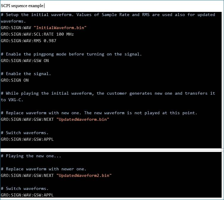
Remote command only
For M9484C, enables or disables the gapless waveform switching. See Gapless Waveform Switching for information on how to use this feature.
SCPI Command | [:SOURce]:GROup<group>:SIGNal[1]:WAVeform:GSWitching[:STATe] ON|OFF|1|0 [:SOURce]:GROup<group>:SIGNal[1]:WAVeform:GSWitching[:STATe]? |
SCPI Example | :GRO:SIGN:WAV:GSW ON :GRO:SIGN:WAV:GSW? |
Dependencies | This setting can be turned on only if the following conditions are met: - The Signals group configuration is Independent. - Enable Vector Modulation is Off. - Waveform File for the signal is selected. |
| Preset | OFF |
| State Saved | Yes |
Initial S/W Revision | A.17.00 |
Remote command only
For M9484C, uploads waveform data in the specified file to be used when switching waveforms. Refer to File Name Variables for information on how to specify a file.
See Gapless Waveform Switching for information on how to use this feature.
SCPI Command | [:SOURce]:GROup<group>:SIGNal[1]:WAVeform:GSWitching:NEXT <filename> |
SCPI Example | :GRO:SIGN:WAV:GSW:NEXT "MyWaveform.wfm" |
Notes | The length of the specified waveform must match that of the initial waveform. |
| Dependencies | This command is applied only if the following conditions are met:
|
Initial S/W Revision | A.17.00 |
Remote command only
For M9484C, switches waveforms between the specified Waveform File and Next Waveform.
See Gapless Waveform Switching for information on how to use this feature.
SCPI Command | [:SOURce]:GROup<group>:SIGNal[1]:WAVeform:GSWitching:APPLy |
SCPI Example | :GRO:SIGN:WAV:GSW:APPL |
| Dependencies | This command is applied only if the following conditions are met:
|
Initial S/W Revision | A.17.00 |
Remote command only
For M9484C, enables or disables the synchronization between channels. Disabling this prevents the signal from restarting due to parameter changes and the phase of signal will be out of sync with other channels.
See Gapless Waveform Switching for information on how to use this feature.
SCPI Command | [:SOURce]:GROup<group>:SIGNal[1]:WAVeform:GSWitching:SYNChronize ON|OFF|1|0 |
SCPI Example | :GRO1:SIGN1:WAV:GSW:SYNC 0 :GRO1:SIGN1:WAV:GSW:SYNC? |
| Dependencies | When Enable Gapless Waveform Switching is OFF, the value is ON and unchangeable. Attempting to set the value to OFF when Enable Gapless Waveform Switching is OFF raises the error 703, "Settings conflict; Gapless Waveform Switching must be enabled before turning off synchronization." |
| Preset | ON |
| State Saved | Yes |
Initial S/W Revision | A.18.00 |
Requires Option EP1.
In use cases where the modulated signal contains component carriers that are spectrally separated within the Occupied Bandwidth, you can specify the Aggregate Active Bandwidth to indicate the how the RF energy is distributed within the Occupied Bandwidth. For example, if you have a two component carrier signal with each carrier 5 MHz wide, spaced 100 MHz apart on center, the Occupied Bandwidth will be 105 MHz and you would set the Aggregate Active Bandwidth to 10 MHz. The Aggregate Active Bandwidth is never greater than the Occupied Bandwidth. Appropriately specifying the Aggregate Active Bandwidth and Occupied Bandwidth may improve the ACPR and EVM performance of the instrument. ![]() View image of example frequency domain.
View image of example frequency domain.
GUI Location | Signals > Mode set to Waveform File >Aggregate Active Bandwidth |
SCPI Command | [:SOURce]:GROup<group>:SIGNal<signal>:WAVeform:AABWidth <freq> [:SOURce]:GROup<group>:SIGNal<signal>:WAVeform:AABWidth? |
SCPI Example | GRO:SIGN:WAV:AABW 5 MHZ GRO:SIGN:WAV:AABW? |
Dependencies | Option EP1 must be present, you can change the value via SCPI however you cannot change the State. |
Preset | 0 |
State Saved | Yes |
Min | 0 Hz |
| Max | For BW, see Vector Modulation Bandwidth Limitations table. |
Couplings | The Aggregate Active Bandwidth must be less than the Occupied Bandwidth. {RD} Limited with no bounce back {/RD} When a new waveform is selected the Aggregate Active Bandwidth values does not change except to apply the limit that the value must not be greater than the Occupied Bandwidth. |
Resolution | 1 Hz |
Backwards Compatibility SCPI | The following commands are not recommended. They are for the convenience of users with existing remote programs developed for earlier versions of the signal generator or ported from a similar product. Alias [:SOURce]:SIGNal[1]:WAVeform:AABWidth to :SOURce:GROup1:SIGNal1:WAVeform:AABWidth Alias [:SOURce]:SIGNal2:WAVeform:AABWidth to :SOURce:GROup2:SIGNal1:WAVeform:AABWidth |
Initial S/W Revision | A.01.00 |
Modified S/W Revision | A.07.00 A.09.00 Added :GROup keyword |
Requires Option EP1.
Select the checkbox to enable (checkmarked) or disable the Aggregate Active Bandwidth. For signals where the modulation fully consumes the Occupied Bandwidth, Aggregate Active Bandwidth should be Off. Aggregate Active Bandwidth should be set to On when the modulation signal does not fully utilize the RF energy of the Occupied Bandwidth.
GUI Location | Signals > Mode set to Waveform File >Aggregate Active Bandwidth > On |
SCPI Command | [:SOURce]:GROup<group>:SIGNal<signal>:WAVeform:AABWidth:STATe ON|OFF|1|0 [:SOURce]:GROup<group>:SIGNal<signal>:WAVeform:AABWidth:STATe? |
SCPI Example | GRO:SIGN:WAV:AABW:STAT ON GRO:SIGN:WAV:AABW:STAT? |
Dependencies | Option EP1 must be present, if you attempt to change the state without Option EP1 the error message is: -221,"Settings Conflict; cannot turn on Aggregate Active Bandwidth, Option EP1 is required." |
Preset | OFF |
State Saved | Yes |
Choices | OFF | ON |
Couplings | When a waveform is selected the state is set to OFF. |
Backwards Compatibility SCPI | The following commands are not recommended. They are for the convenience of users with existing remote programs developed for earlier versions of the signal generator or ported from a similar product. Alias [:SOURce]:SIGNal[1]:WAVeform:AABWidth:STATe to :SOURce:GROup1:SIGNal1:WAVeform:AABWidth:STATe Alias [:SOURce]:SIGNal2:WAVeform:AABWidth:STATe to :SOURce:GROup2:SIGNal1:WAVeform:AABWidth:STATe |
Initial S/W Revision | A.01.00 |
Modified S/W Revision | A.07.00 A.09.00 Added :GROup keyword |
When a *.bnd waveform file is selected, this command should be used to restore the calibrated state of the bonded signal.
This command is only valid when a *.bnd file is loaded.
GUI Location | System Menu > Configure Channels > Bonded > Signals > Recall Calibrated State |
SCPI Command | [:SOURce]:GROup<group>:CBONded:INSTrument:STATe:RECall |
SCPI Example | GRO:CBON:INST:STAT:REC |
SCPI Change | [:SOURce]:CBONded<bondingset>:INSTrument:STATe:RECall has been changed to [:SOURce]:GROup<group>:CBONded:INSTrument:STATe:RECall. Prior use of :SOUR:CBON:INST:STAT:REC or :SOUR:CBON1:INST:STAT:REC is now :SOUR:GRO1:CBON:INST:STAT:REC. |
Initial S/W Revision | A.07.00 |
Modified S/W Revision | A.10.00 Changed SCPI: Added :GROup<group> and removed <bondingset> from :CBONded |
Marker Routing applies to Waveform File and Real Time signal modes.
SCPI commands directly tied to this GUI are not defined, rather the event connectors SCPI commands are used to setup the marker routine.
Some Vector Modulation Signal Modes provide a mechanism to output a TTL-like signal synchronized with the modulation playback. Depending on the capability provided by the instrument, up to four markers can be provided. See Waveform Header.
For the M9484C, a Marker can be routed to the Event connectors of the instrument:
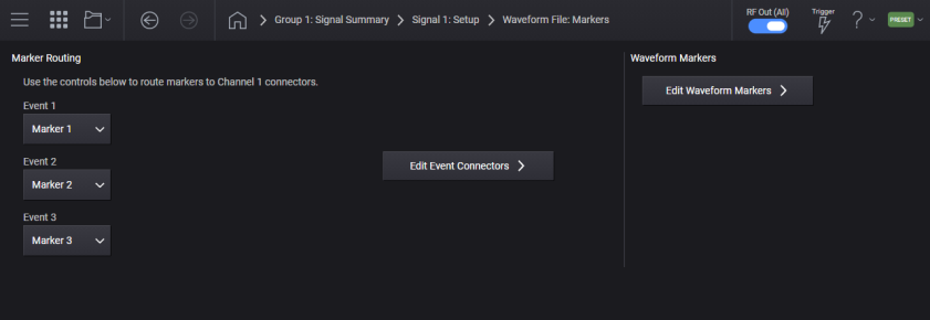
Event 1 applies to the M9484C only.
Routes a marker of signal<signal> to Event 1.
GUI Location | Signals > Signal Summary selection > Mode set to Waveform File or to Real-Time > Markers > Event 1 |
Preset | Marker 1 for signal 1 NONE for other signals |
Choices | None | Marker 1 | Marker 2 | Marker 3 | Marker 4 |
Initial S/W Revision | A.10.00 |
Refer to Events in the Connectors topic.
Event 2 applies to the M9484C only.
Routes a marker of signal<signal> to Event 2.
GUI Location | Signals > Signal Summary selection > Mode set to Waveform File or to Real-Time > Markers > Event 2 |
Preset | Marker 2 for signal 1 NONE for other signals |
Choices | None | Marker 1 | Marker 2 | Marker 3 | Marker 4 |
Initial S/W Revision | A.10.00 |
Refer to Events in the Connectors topic.
Event 3 applies to the M9484C only.
Routes a marker of signal<signal> to Event 3.
GUI Location | Signals > Signal Summary selection > Mode set to Waveform File or to Real-Time > Markers > Event 3 |
Preset | Marker 3 for signal 1 NONE for other signals |
Choices | None | Marker 1 | Marker 2 | Marker 3 | Marker 4 |
Initial S/W Revision | A.10.00 |
Refer to Events in the Connectors topic.
Edit Event Connectors applies to the M9484C only.
Accesses the Event Configuration screen.
Refer to Events in the Connectors topic.
Click this button to access the Marker Editor.
See also Marker Editing Using SCPI.
Marker Routing applies to Waveform File and Real Time signal modes.
Some Vector Modulation Signal Modes provide a mechanism to output a TTL-like signal synchronized with the modulation playback. Depending on the capability provided by the instrument, up to four markers can be provided. See Waveform Header.
Provided to allow programmatic compatibility with other Keysight Technologies signal generators.
SCPI Command | [:SOURce]:GROup<group>:SIGNal<signal>:WAVeform:MDEStination:ALCHold NONE [:SOURce]:GROup<group>:SIGNal<signal>:WAVeform:MDEStination:ALCHold? |
SCPI Example | GRO:SIGN:WAV:MDES:ALCH NONE GRO:SIGN:WAV:MDES:ALCH? |
Note | ALC Hold is NONE and not changeable, attempting to change the value generates the standard SCPI error. |
Preset | None |
Choices | None |
State Saved | Yes |
Backwards Compatibility SCPI | The following commands are not recommended. They are for the convenience of users with existing remote programs developed for earlier versions of the signal generator or ported from a similar product. [:SOURce]:RADio[1]:ARB:MDEStination:ALCHold Alias [:SOURce]:SIGNal[1]:WAVeform:MDEStination:ALCHold to :SOURce:GROup1:SIGNal1:WAVeform:MDEStination:ALCHold Alias [:SOURce]:SIGNal2:WAVeform:MDEStination:ALCHold to :SOURce:GROup2:SIGNal1:WAVeform:MDEStination:ALCHold Alias [:SOURce]:SIGNal[1]:CMODulation:MDEStination:ALCHold to :SOURce:GROup1:SIGNal1:WAVeform:MDEStination:ALCHold Alias [:SOURce]:SIGNal2:CMODulation:MDEStination:ALCHold to :SOURce:GROup2:SIGNal1:WAVeform:MDEStination:ALCHold Alias [:SOURce]:SIGNal[1]:NR5G:MDEStination:ALCHold to :SOURce:GROup1:SIGNal1:WAVeform:MDEStination:ALCHold Alias [:SOURce]:SIGNal2:NR5G:MDEStination:ALCHold to :SOURce:GROup2:SIGNal1:WAVeform:MDEStination:ALCHold |
Initial S/W Revision | A.01.00 |
Modified S/W Revision | A.09.00 Added :GROup keyword |
Provided to allow programmatic compatibility with other Keysight Technologies signal generators.
SCPI Command | [:SOURce]:GROup<group>:SIGNal<signal>:WAVeform:MDEStination:PULSe NONE [:SOURce]:GROup<group>:SIGNal<signal>:WAVeform:MDEStination:PULSe? |
SCPI Example | GRO:SIGN:WAV:MDES:PULS None GRO:SIGN:WAV:MDES:PULS? |
Note | PULSe is NONE and not changeable, attempting to change the value generates the standard SCPI error. |
Preset | None |
Choices | None |
State Saved | Yes |
Backwards Compatibility SCPI | The following commands are not recommended. They are for the convenience of users with existing remote programs developed for earlier versions of the signal generator or ported from a similar product. [:SOURce]:RADio[1]:ARB:MDEStination:PULSe Alias [:SOURce]:SIGNal[1]:WAVeform:MDEStination:PULSe to :SOURce:GROup1:SIGNal1:WAVeform:MDEStination:PULSe Alias [:SOURce]:SIGNal2:WAVeform:MDEStination:PULSe to :SOURce:GROup2:SIGNal1:WAVeform:MDEStination:PULSe Alias [:SOURce]:SIGNal[1]:CMODulation:MDEStination:PULSe to :SOURce:GROup1:SIGNal1:WAVeform:MDEStination:PULSe Alias [:SOURce]:SIGNal2:CMODulation:MDEStination:PULSe to :SOURce:GROup2:SIGNal1:WAVeform:MDEStination:PULSe Alias [:SOURce]:SIGNal[1]:NR5G:MDEStination:PULSe to :SOURce:GROup1:SIGNal1:WAVeform:MDEStination:PULSe Alias [:SOURce]:SIGNal2:NR5G:MDEStination:PULSe to :SOURce:GROup2:SIGNal1:WAVeform:MDEStination:PULSe |
Initial S/W Revision | A.01.00 |
Modified S/W Revision | A.09.00 Added :GROup keyword |
Remote command only.
Provided to allow programmatic compatibility with other Keysight Technologies signal generators.
SCPI Command | [:SOURce]:GROup<group>:SIGNal<signal>:WAVeform:PULSe:POLarity POSitive [:SOURce]:GROup<group>:SIGNal<signal>:WAVeform:PULSe:POLarity? |
SCPI Example | GRO:SIGN:WAV:PULS:POL POS GRO:SIGN:WAV:PULS:POL? |
Note | POLarity is POSitive and not changeable, attempting to change the value generates the standard SCPI error. |
Preset | POSitive |
Range | Positive |
State Saved | No |
Initial S/W Revision | A.02.00 |
Backwards Compatibility SCPI | The following commands are not recommended. They are for the convenience of users with existing remote programs developed for earlier versions of the signal generator or ported from a similar product. Alias [:SOURce]:SIGNal[1]:WAVeform:PULSe:POLarity to :SOURce:GROup1:SIGNal1:WAVeform:PULSe:POLarity Alias [:SOURce]:SIGNal2:WAVeform:PULSe:POLarity to :SOURce:GROup2:SIGNal1:WAVeform:PULSe:POLarity Alias [:SOURce]:SIGNal[1]:CMODulation:PULSe:POLarity to :SOURce:GROup1:SIGNal1:WAVeform:PULSe:POLarity Alias [:SOURce]:SIGNal2:CMODulation:PULSe:POLarity to :SOURce:GROup2:SIGNal1:WAVeform:PULSe:POLarity Alias [:SOURce]:SIGNal[1]:NR5G:PULSe:POLarity to :SOURce:GROup1:SIGNal1:WAVeform:PULSe:POLarity Alias [:SOURce]:SIGNal2:NR5G:PULSe:POLarity to :SOURce:GROup2:SIGNal1:WAVeform:PULSe:POLarity |
Initial S/W Revision | A.01.00 |
Modified S/W Revision | A.09.00 Added :GROup keyword, aliased CMODulation and NR5G to WAVeform |
Remote command only.
Provided to allow programmatic compatibility with other Keysight Technologies signal generators.
SCPI Command | [:SOURce]:GROup<group>:SIGNal<signal>:WAVeform:SYNC:POLarity NEGative|POSitive [:SOURce]:GROup<group>:SIGNal<signal>:WAVeform:SYNC:POLarity? |
SCPI Example | GRO:SIGN:WAV:SYNC:POL POS GRO:SIGN:WAV:SYNC:POL? |
Preset | POSitive |
State Saved | Yes |
Backwards Compatibility SCPI | The following commands are not recommended. They are for the convenience of users with existing remote programs developed for earlier versions of the signal generator or ported from a similar product. Alias [:SOURce]:SIGNal[1]:WAVeform:SYNC:POLarity to :SOURce:GROup1:SIGNal1:WAVeform:SYNC:POLarity Alias [:SOURce]:SIGNal2:WAVeform:SYNC:POLarity to :SOURce:GROup2:SIGNal1:WAVeform:SYNC:POLarity Alias [:SOURce]:SIGNal[1]:CMODulation:SYNC:POLarity to :SOURce:GROup1:SIGNal1:WAVeform:SYNC:POLarity Alias [:SOURce]:SIGNal2:CMODulation:SYNC:POLarity to :SOURce:GROup2:SIGNal1:WAVeform:SYNC:POLarity Alias [:SOURce]:SIGNal[1]:NR5G:SYNC:POLarity to :SOURce:GROup1:SIGNal1:WAVeform:SYNC:POLarity Alias [:SOURce]:SIGNal2:NR5G:SYNC:POLarity to :SOURce:GROup2:SIGNal1:WAVeform:SYNC:POLarity |
Initial S/W Revision | A.01.00 |
Modified S/W Revision | A.09.00 Added :GROup keyword, aliased CMODulation and NR5G to WAVeform |
Provided to allow programmatic compatibility with other Keysight Technologies signal generators.
SCPI Command | [:SOURce]:GROup<group>:SIGNal<signal>:WAVeform:MDEStination:SYNC NONE|M1|M2|M3|M4 [:SOURce]:GROup<group>:SIGNal<signal>:WAVeform:MDEStination:SYNC? |
SCPI Example | GRO:SIGN:WAV:MDES:SYNC M1 GRO:SIGN:WAV:MDES:SYNC? |
Preset | Marker1 (M1) |
Choices | None | Marker1 | Marker2 | Marker3 | Marker4 |
State Saved | Yes |
Backwards Compatibility SCPI | The following commands are not recommended. They are for the convenience of users with existing remote programs developed for earlier versions of the signal generator or ported from a similar product. Alias [:SOURce]:SIGNal[1]:CMODulation:TRIGger:SYNC:MARKer to :SOURce:GROup1:SIGNal1:WAVeform:MDEStination:SYNC Alias [:SOURce]:SIGNal2:CMODulation:TRIGger:SYNC:MARKer to :SOURce:GROup2:SIGNal1: WAVeform:MDEStination:SYNC Alias [:SOURce]:SIGNal[1]:NR5G:TRIGger:SYNC:MARKer to :SOURce:GROup1:SIGNal1: WAVeform:MDEStination:SYNC Alias [:SOURce]:SIGNal2:NR5G:TRIGger:SYNC:MARKer to :SOURce:GROup2:SIGNal1: WAVeform:MDEStination:SYNC Alias [:SOURce]:SIGNal[1]:WAVeform:TRIGger:SYNC:MARKer to :SOURce:GROup1:SIGNal1: WAVeform:MDEStination:SYNC Alias [:SOURce]:SIGNal2:WAVeform:TRIGger:SYNC:MARKer to :SOURce:GROup2:SIGNal1: WAVeform:MDEStination:SYNC
For M9484C: [:SOURce]:GROup[1]:SIGNal[1]:WAVeform:MDEStination:SYNC NONE|M1|M2|M3|M4 will be aliased to :ROUTe:CONNectors:RF1:EVENt1 NONE| S1M1| S1M2| S1M3| S1M4 [:SOURce]:GROup2:SIGNal[1]:WAVeform:MDEStination:SYNC NONE|M1|M2|M3|M4 will be aliased to :ROUTe:CONNectors:RF2:EVENt1 NONE| S1M1| S1M2| S1M3| S1M4 [:SOURce]:SIGNal[1]:WAVeform:TRIGger:SYNC:MARKer NONE|M1|M2|M3|M4 will be aliased to :ROUTe:CONNectors:RF1:EVENt1 NONE| S1M1| S1M2| S1M3| S1M4 [:SOURce]:SIGNal2:WAVeform:TRIGger:SYNC:MARKer NONE|M1|M2|M3|M4 will be aliased to :ROUTe:CONNectors:RF2:EVENt1 NONE| S1M1| S1M2| S1M3| S1M4 |
Initial S/W Revision | A.01.00 |
Modified S/W Revision | A.09.00 Added :GROup keyword |
Click this button to access the Marker Editor.
See also Marker Editing Using SCPI.
Remote command only.
This is a command for compatibility with the N5181B/82B/83B MXG.
When set to on, Mode is set to Waveform File and vector modulation is enabled. It is off when Mode is not set to Waveform File or vector modulation is disabled.
SCPI Command | [:SOURce]:RADio:ARB[:STATe] ON|OFF|1|0 [:SOURce]:RADio:ARB[:STATe]? |
SCPI Example | :RAD:ARB 1 :RAD:ARB? |
Preset | OFF |
State Saved | No |
Initial S/W Revision | A.01.00 |
Remote command only.
Query only command. Returns the waveform quantum. Waveform length needs to be a multiple of this number.
SCPI Command | [:SOURce]:GROup<group>:SIGNal<signal>:WAVeform:INFormation:QUANtum? |
SCPI Example | GRO:SIGN:WAV:INF:QUAN? |
State Saved | No |
Notes | For M9484C the quantum is 1 |
Backwards Compatibility SCPI | The following commands are not recommended. They are for the convenience of users with existing remote programs developed for earlier versions of the signal generator or ported from a similar product. Alias [:SOURce]:SIGNal[1]:WAVeform:INFormation:QUANtum? to :SOURce:GROup1:SIGNal1:WAVeform:INFormation:QUANtum? Alias [:SOURce]:SIGNal2:WAVeform:INFormation:QUANtum? to :SOURce:GROup2:SIGNal1:WAVeform:INFormation:QUANtum? |
Initial S/W Revision | A.02.00 |
Modified S/W Revision | A.09.00 Added :GROup keyword |
Remote command only.
Query only command. Returns the minimum length of waveform segment. Waveform may not be played when its length is less than this number.
A segment is a part of waveform sequence. The minimum segment is the shortest segment that plays correctly. This is usually the same as the minimum waveform length as playing a "waveform" is internally the same as playing a sequence of one segment.
SCPI Command | [:SOURce]:GROup<group>:SIGNal<signal>:WAVeform:INFormation:SLENgth:MINimum? |
SCPI Example | GRO:SIGN:WAV:INF:SLEN:MIN? |
State Saved | No |
Notes | For M9484C minimum is 512 |
Backwards Compatibility SCPI | The following commands are not recommended. They are for the convenience of users with existing remote programs developed for earlier versions of the signal generator or ported from a similar product. Alias [:SOURce]:SIGNal[1]:WAVeform:INFormation:SLENgth:MINimum? to :SOURce:GROup1:SIGNal1:WAVeform:INFormation:SLENgth:MINimum? Alias [:SOURce]:SIGNal2:WAVeform:INFormation:SLENgth:MINimum? to :SOURce:GROup2:SIGNal1:WAVeform:INFormation:SLENgth:MINimum? |
Initial S/W Revision | A.02.00 |
Modified S/W Revision | A.09.00 Added :GROup keyword |
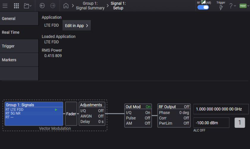
For M9484C with N7631APPC, displays the name of the currently loaded real-time application.
GUI Location | Signals > Real-Time > Loaded Application |
State Saved | No |
Initial S/W Revision | A.10.00 |
Query only. Returns the currently used real-time application.
When no application is used, "---" is displayed. When the value is different from the Loaded Application, Enable Vector Modulation Signal cannot be turned on.
SCPI Command | [:SOURce]:GROup<group>:SIGNal<signal>:RTIMe:APPLication? |
SCPI Example | GRO:SIGN:RTIM:APPL? |
State Saved | No |
Initial S/W Revision | A.14.00 |
Query only command.
For M9484C with N7631APPC, returns the sample rate of the modulating waveform set by the real-time application GUI. Accepts frequency units (e.g., 100 MHz).
SCPI Command | [:SOURce]:GROup<group>:SIGNal<signal>:RTIMe:SCLock:RATE? |
SCPI Example | GRO:SIGN:RTIM:SCL:RATE? |
Preset | For M9484C: Options R25/R2E = 3.0 GHz, R10/R1E = 1228.8 MHz, B5X = 600 MHz, B2X = 300 MHz, B1X = 200 MHz |
State Saved | Yes |
Min | For M9484C: 100 Hz |
Max | For M9484C: Options R25/R2E = 3.0 GHz, R10/R1E = 1228.8 MHz, B5X = 600 MHz, B2X = 300 MHz, B1X = 200 MHz |
Resolution | 0.000001 Hz |
Initial S/W Revision | A.10.00 |
Query only command.
For M9484C with N7631APPC, returns the calculated value set by the real-time application GUI.
GUI Location | Signals > Real-Time > RMS Power |
SCPI Command | [:SOURce]:GROup<group>:SIGNal<signal>:RTIMe:RMS? |
SCPI Example | GRO:SIGN:RTIM:RMS? |
Preset | 1 |
State Saved | Yes |
Min | 0.1 |
Max | 1.414213562 |
Resolution | 0.000000001 |
Initial S/W Revision | A.10.00 |
Query only command.
For M9484C with N7631APPC, returns the scale factor of the modulating waveform set by the real-time application GUI in percent.
SCPI Command | [:SOURce]:GROup<group>:SIGNal<signal>:RTIMe:SCALe? |
SCPI Example | GRO:SIGN:RTIM:SCAL? |
Preset | 100 |
State Saved | Yes |
Min | 1 |
Max | 100 |
Resolution | 0.01 |
Initial S/W Revision | A.10.00 |
Query only command.
For M9484C with N7631APPC, returns the occupied bandwidth of the modulating waveform set by the real-time application.
GUI Location | Signals > Real-Time > Occupied Bandwidth |
SCPI Command | [:SOURce]:GROup<group>:SIGNal<signal>:RTIMe:OBWidth? |
SCPI Example | GRO:SIGN:RTIM:OBW? |
Preset | 0 |
State Saved | Yes |
Min | 0 |
Max | For M9484C: Options R25, R2E = 2500 MHz Options R10, R1E = 1024 MHz Options B5X = 500 MHz Options B2X = 250 MHz Options B1X = 160 MHz |
Resolution | 1 Hz |
Initial S/W Revision | A.10.00 |
Additive white Gaussian noise (AWGN) is a basic noise node for thermal noise in communication channels. The modifiers denote specific characteristics:
Additive is added to any noise that might be intrinsic to the information system.
White has uniform to power across the frequency band for the information system. That is, the power spectral density is flat, so the auto correlation of the noise in the time domain is zero for any non-zero time offset.
Gaussian has a normal distribution in the time domain with an average time domain value of zero.
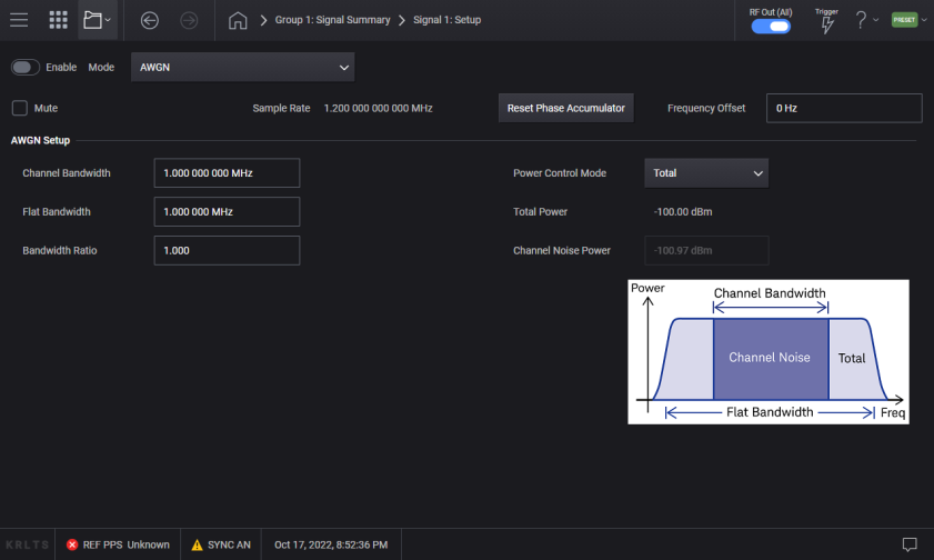
Sets the channel bandwidth over which the AWGN is applied. The channel bandwidth is the portion of the bandwidth specified by the bandwidth ratio.
GUI Location | Signals > General tab > Mode set to AWGN > AWGN tab > Channel Bandwidth |
SCPI Command | [:SOURce]:GROup<group>:SIGNal<signal>:AWGN:CBWidth <freq> [:SOURce]:GROup<group>:SIGNal<signal>:AWGN:CBWidth? |
SCPI Example | GRO:SIGN:AWGN:CBW 10 Hz GRO:SIGN:AWGN:CBW? |
Preset | 1 MHz |
State Saved | Yes |
Min | 1 Hz |
| Max | For BW, see Vector Modulation Bandwidth Limitations table. |
Resolution | 0.001 Hz |
Step Increment | 5 kHz |
Backwards Compatibility SCPI | The following commands are not recommended. They are for the convenience of users with existing remote programs developed for earlier versions of the signal generator or ported from a similar product. [:SOURce]:RADio:AWGN:RT:CBWidth Alias [:SOURce]:SIGNal[1]:AWGN[:RT]:CBWidth to :SOURce:GROup1:SIGNal1:AWGN[:RT]:CBWidth Alias [:SOURce]:SIGNal2:AWGN[:RT]:CBWidth to :SOURce:GROup2:SIGNal1:AWGN[:RT]:CBWidth |
Initial S/W Revision | A.03.00 |
Modified S/W Revision | A.09.00 Added :GROup keyword |
Sets the power control to either of the following two modes:
Total : Selects the displayed instrument power for control.
Channel Noise: Selects the channel noise power for control. The channel noise power is settable from the front panel only when the Power Control mode is set to Channel Noise.
GUI Location | Signals > General tab > Mode set to AWGN > AWGN tab > Power Control Mode |
SCPI Command | [:SOURce]:GROup<group>:SIGNal<signal>:AWGN:POWer:CONTrol[:MODE] TOTal|NCHannel [:SOURce]:GROup<group>:SIGNal<signal>:AWGN:POWer:CONTrol[:MODE]? |
SCPI Example | GRO:SIGN:AWGN:POW:CONT TOT GRO:SIGN:AWGN:POW:CONT? |
| Dependencies | In case Absolute Power Mode is set to Off:
|
Preset | TOT |
Choices | Total | Channel Noise |
Backwards Compatibility SCPI | The following commands are not recommended. They are for the convenience of users with existing remote programs developed for earlier versions of the signal generator or ported from a similar product. [:SOURce]:RADio:AWGN:RT:POWer:CONTrol[:MODE] Alias [:SOURce]:SIGNal[1]:AWGN[:RT]:POWer:CONTrol[:MODE] to :SOURce:GROup1:SIGNal1:AWGN[:RT]:POWer:CONTrol[:MODE] Alias [:SOURce]:SIGNal2:AWGN[:RT]:POWer:CONTrol[:MODE] to :SOURce:GROup2:SIGNal1:AWGN[:RT]:POWer:CONTrol[:MODE] |
Initial S/W Revision | A.03.00 |
Modified S/W Revision | A.09.00 Added :GROup keyword |
Sets the flat bandwidth value of the stand-alone real-time noise.
GUI Location | Signals > General tab > Mode set to AWGN > AWGN tab > Flat Bandwidth |
SCPI Command | [:SOURce]:GROup<group>:SIGNal<signal>:AWGN:BANDwidth|BWIDth <freq> [:SOURce]:GROup<group>:SIGNal<signal>:AWGN:BANDwidth|BWIDth? |
SCPI Example | GRO:SIGN:AWGN:BAND 10 Hz GRO:SIGN:AWGN:BAND? |
Preset | 1 MHz |
State Saved | Yes |
Min | 1 Hz |
| Max | For BW, see Vector Modulation Bandwidth Limitations table. |
Resolution | 0.001 Hz |
Step Increment | 5 kHz |
Backwards Compatibility SCPI | The following commands are not recommended. They are for the convenience of users with existing remote programs developed for earlier versions of the signal generator or ported from a similar product. [:SOURce]:RADio:AWGN:RT:BANDwidth|BWIDth Alias [:SOURce]:SIGNal[1]:AWGN[:RT]:BANDwidth|BWIDth to :SOURce:GROup1:SIGNal1:AWGN[:RT]:BANDwidth Alias [:SOURce]:SIGNal2:AWGN[:RT]:BANDwidth|BWIDth to :SOURce:GROup2:SIGNal1:AWGN[:RT]:BANDwidth |
Initial S/W Revision | A.03.00 |
Modified S/W Revision | A.09.00 Added :GROup keyword |
Sets the total noise power.
This parameter is editable only when Absolute Power Mode is On and Power Control Mode is Total.
GUI Location | Signals > General tab > Mode set to AWGN > AWGN tab > Total Noise Power |
SCPI Command | [:SOURce]:GROup<group>:SIGNal<signal>:AWGN:POWer:NOISe:TOTal <ampl> [:SOURce]:GROup<group>:SIGNal<signal>:AWGN:POWer:NOISe:TOTal? |
SCPI Example | GRO:SIGN:AWGN:POW:NOIS:TOT -10 dBm GRO:SIGN:AWGN:POW:NOIS:TOT? |
| Couplings | When Absolute Power Control is ON:
When Absolute Power Control is OFF:
|
| Notes | Total Noise Power is affected by the RF Channel Power, Amplitude Reference and Amplitude Offset. |
Preset | -100.00 dBm |
Min | Minimum value of Power when vector modulation is on or Power Control Mode is Total. |
Max | Maximum value of Power when vector modulation is on or Power Control Mode is Total. |
Resolution | 0.01 dB |
Initial S/W Revision | A.03.00 |
Modified S/W Revision | A.17.00 - Changed Parameter Name and added SCPI |
Sets the amount of Channel Bandwidth compared to the amount of Flat Bandwidth.
When Bandwidth Ratio is changed, Flat Bandwidth is updated. If Flat Bandwidth reaches its limit value, Bandwidth Ratio is clipped using that value.
GUI Location | Signals > General tab > Mode set to AWGN > AWGN tab > Bandwidth Ratio |
SCPI Command | [:SOURce]:GROup<group>:SIGNal<signal>:AWGN:RATio [:SOURce]:GROup<group>:SIGNal<signal>:AWGN:RATio? |
SCPI Example | GRO:SIGN:AWGN:RAT 10 GRO:SIGN:AWGN:RAT? |
Preset | 1.0 |
State Saved | Yes |
Min | 1.0 |
Max | If Flat Bandwidth reaches its limit value during updating Bandwidth Ratio, Bandwidth Ratio is clipped. min(100, (Maximum of Flat Bandwidth)/(Channel Bandwidth)) |
Resolution | 0.001 |
Step Increment | 1 |
Backwards Compatibility SCPI | The following commands are not recommended. They are for the convenience of users with existing remote programs developed for earlier versions of the signal generator or ported from a similar product. [:SOURce]:RADio:AWGN:RT:RATio Alias [:SOURce]:SIGNal[1]:AWGN[:RT]:RATio to :SOURce:GROup1:SIGNal1:AWGN[:RT]:RATio Alias [:SOURce]:SIGNal2:AWGN[:RT]:RATio to :SOURce:GROup2:SIGNal1:AWGN[:RT]:RATio |
Initial S/W Revision | A.03.00 |
Modified S/W Revision | A.09.00 Added :GROup keyword |
Sets the power within the channel bandwidth. The instrument power is changed in relation to this setting when AWGN is selected. The channel noise power is settable from the front panel only when the Power Control mode is set to Channel Noise.
GUI Location | Signals > General tab > Mode set to AWGN > AWGN tab > Channel Noise Power |
SCPI Command | [:SOURce]:GROup<group>:SIGNal<signal>:AWGN:POWer:NOISe:CHANnel <ampl> [:SOURce]:GROup<group>:SIGNal<signal>:AWGN:POWer:NOISe:CHANnel? |
SCPI Example | GRO:SIGN:AWGN:POW:NOIS:CHAN -30 dBm GRO:SIGN:AWGN:POW:NOIS:CHAN? |
Preset | For M9484C: -100.79 dBm |
State Saved | Yes |
Min | 1.2 and 1.25 are, respectively, converted to approximately 0.79 dB and 0.97 dB. |
Max | 1.2 and 1.25 are, respectively, converted to approximately 0.79 dB and 0.97 dB. |
Resolution | 0.01 dB |
Step Increment | 5 dB |
Backwards Compatibility SCPI | The following commands are not recommended. They are for the convenience of users with existing remote programs developed for earlier versions of the signal generator or ported from a similar product. [:SOURce]:RADio:AWGN:RT:POWer:NOISe:CHANnel Alias [:SOURce]:SIGNal[1]:AWGN[:RT]:POWer:NOIse:CHANnel to :SOURce:GROup1:SIGNal1:AWGN[:RT]:POWer:NOIse:CHANnel Alias [:SOURce]:SIGNal2:AWGN[:RT]:POWer:NOIse:CHANnel to :SOURce:GROup2:SIGNal1:AWGN[:RT]:POWer:NOIse:CHANnel |
Initial S/W Revision | A.03.00 |
Modified S/W Revision | A.09.00 Added :GROup keyword A.17.00 - Revised Preset, Min, and Max values |
Remote command only.
This is a command for compatibility with N5181B/82B/83B MXG.
When set to on, Mode is set to stand-alone AWGN and vector modulation is enabled.
It is off when Mode is not set to stand-alone AWGN or when vector modulation is disabled.
SCPI Command | [:SOURce]:RADio:AWGN:RT[:STATe] ON|OFF|1|0 [:SOURce]:RADio:AWGN:RT[:STATe]? |
SCPI Example | :RAD:AWGN:RT 1 :RAD:AWGN:RT? |
Preset | OFF |
State Saved | No |
Initial S/W Revision | A.03.00 |
Remote command only.
This command enables or disables the waveform sweep function, when the signal generator is in the List sweep mode.
SCPI Command | [:SOURce][:RF<channel>]:RADio:LARB[:STATe] ON|OFF|1|0 [:SOURce][:RF<channel>]:RADio:LARB[:STATe]? |
SCPI Example | :RAD:LARB 1 :RAD:LARB? |
| Dependencies | When the Sweep Type is Step, this setting cannot be turned on and reports a setting conflict warning message. |
Preset | OFF |
| Coupling | When Waveform Sweep State is set to OFF, LARB State is set to OFF This command couples to Waveform Sweep State and List Sweep Enable. When LARB State is set to OFF, Waveform Sweep State is set to OFF. When LARB State is set to ON, Waveform Sweep State is set to ON and List Sweep State is turned ON. |
| Backwards Compatibility SCPI | N51xxB: [:SOURce]:RADio:LARB[:STATe] |
State Saved | Yes |
Initial S/W Revision | A.16.00 |
For M9484C with Option DS1.
The ODI Streaming screen is available when you set the Connectors > ODI Streaming > Enable Port to 'On' and the Signal Setup > General > Mode to 'ODI Streaming'.
For more information, refer to Steps to Configure and Enable ODI Streaming.
Sets the RMS on the modulating waveform.
SCPI Command | [:SOURce]:GROup<group>:SIGNal<signal>:ODIStreaming:RMS <real> [:SOURce]:GROup<group>:SIGNal<signal>:ODIStreaming:RMS? |
SCPI Example | GRO:SIGN:ODIS:RMS 1 GRO:SIGN:ODIS:RMS? |
Preset | 1 |
State Saved | Yes |
Min | 0.1 |
Max | 1.414213562 |
Resolution | 0.000000001 |
Initial S/W Revision | A.16.00 |
Sets the scale factor of the modulating waveform in percent.
SCPI Command | [:SOURce]:GROup<group>:SIGNal<signal>:ODIStreaming:SCALe <real> [:SOURce]:GROup<group>:SIGNal<signal>:ODIStreaming:SCALe? |
SCPI Example | GRO:SIGN:ODIS:SCAL 100 GRO:SIGN:ODIS:SCAL? |
Preset | 100 For M9484C: 70 |
State Saved | Yes |
Min | 1 |
Max | 100 |
Resolution | 0.01 |
Initial S/W Revision | A.16.00 |
Sets the occupied bandwidth of vector modulated signal.
SCPI Command | [:SOURce]:GROup<group>:SIGNal<signal>:ODIStreaming:OBWidth <freq> [:SOURce]:GROup<group>:SIGNal<signal>:ODIStreaming:OBWidth? |
SCPI Example | GRO:SIGN:ODIS:OBW 140 kHz GRO:SIGN:ODIS:OBW? |
Preset | 0 |
State Saved | Yes |
Min | 0 Hz |
Max |
|
Resolution | 1 Hz |
Initial S/W Revision | A.16.00 |
Click this button to quickly access the Connectors > ODI Streaming screen using which you can configure ODI Connector settings and also Enable ODI Port for the channel.
Applies to M9484C only.
The Envelope Tracking screens are available when you set the Signal Setup > General > Mode to 'Envelope Tracking'.
For more information, refer to Envelope Tracking.
Instrument Nonlinear Correction
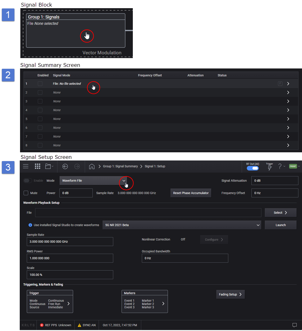
 Trigger button .