Connector routing is supported only on the M9484C. Connector routing is used to associate the physical connectors to features of signal generation.
|
STrig (Sync Trigger) |
||||
|---|---|---|---|---|
For the M9484C, Trigger Connectors can be used for routing as input or output. The available connectors are based on the instrument’s channels and options:
For channel 1 without Option AN1, and channels 2, 3, or 4, the connectors are:
Trig 1, Trig 2, Trig 3
For channel 1 with Option AN1 the connectors are:
Trig 1, Trig A, Trig B, Trig C, and AIO 1 through AIO 12
Connectors Trig A, Trig B, Trig C output bandwidth is limited to 100 MHz; when they are set for output, 3.3 V is the high voltage
Connectors AIO 1 through AIO 12 the input bandwidth is limited to 1 MHz
Via SCPI, the connectors are referenced by a number; 1 to the maximum number of connectors. A SCPI command can be used to provide the connector label for the corresponding number.
|
GUI Location |
System Menu (triple bar icon) > Connectors > Trigger Input tab > External Trigger Source |
|
SCPI Command |
:ROUTe[:CONNectors][:RF<channel>]:TRIG<connector>:LABel? |
|
SCPI Example |
ROUT:TRIG:LAB? |
|
Notes |
The query result will be the labels on the front or rear panel of the instrument. The return value is a string that may contain whitespace characters; for example "Trig A". For M9484C: For Channel 1 without Option AN1, and channels 2, 3, 4: 1 = "Trig 1" 2 = "Trig 2" 3 = "Trig 3" For Channel 1 with Option AN1: 1 = "Trig 1" 4 = "Trig A" 5 = "Trig B" 6 = "Trig C" 7 = "AIO 1" 8 = "AIO 2" … 18 = "AIO 12" Thus: RF1:TRIG[1]|4|5|6|7|8|9|10|11|12|13|14|15|16|17|18 are available connectors when Option AN1 is present RF1 available connectors without Option AN1 are TRIG[1]|2|3 RF2|3|4 available connectors are TRIG[1]|2|3 Attempting to send TRIG<number> for connectors that don’t exist on the instrument will generate an Execution Error. |
|
State Saved |
N/A |
|
Initial S/W Revision |
A.09.00 |
Supported only on the M9484C.
The physical trigger connectors can be used as inputs or outputs. As trigger inputs their operation is applicable when the Configuration Group for the channel is Independent. When the Configuration Group is not Independent
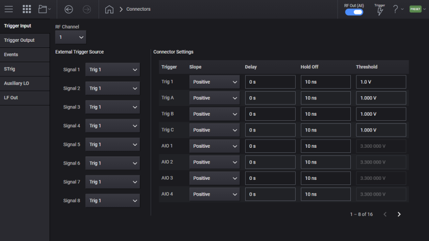
When a trigger connector is used as an input, the following settings can be configured.
For the M9484C, sets the polarity of the signal input at the channel’s trigger connector.
|
GUI Location |
System Menu (triple bar icon) > Connectors > Trigger Input tab > Slope |
|
SCPI Command |
:ROUTe[:CONNectors][:RF<channel>]:TRIG<connector>:INPut:SLOPe POSitive|NEGative :ROUTe[:CONNectors][:RF<channel>]:TRIG<connector>:INPut:SLOPe? |
|
SCPI Example |
ROUT:CONN:RF1:TRIG1:INP:SLOP NEG ROUT:CONN:RF1:TRIG1:INP:SLOP? |
|
Notes |
Attempting to send TRIG<number> for connectors that don’t exist on the instrument will generate an Execution Error. |
|
Preset |
POSitive |
|
Range |
Negative | Positive |
|
State Saved |
Yes |
|
Initial S/W Revision |
A.09.00 |
For the M9484C, sets the input delay of a trigger connector.
|
GUI Location |
System Menu (triple bar icon) > Connectors > Trigger Input tab> Delay |
|
SCPI Command |
:ROUTe[:CONNectors][:RF<channel>]:TRIG<connector>:INPut:DELay timeSec :ROUTe[:CONNectors][:RF<channel>]:TRIG<connector>:INPut:DELay? |
|
SCPI Example |
ROUT:CONN:RF1:TRIG1:INP:DEL 5 us ROUT:CONN:RF1:TRIG1:INP:DEL? |
|
Notes |
Attempting to send TRIG<number> for connectors that don’t exist on the instrument will generate an Execution Error. |
|
Preset |
0 s |
|
State Saved |
Yes |
|
Min |
0 s |
|
Max |
For M9484C: 6.825 us |
|
Resolution |
For M9484C: 1.666 ns |
|
Initial S/W Revision |
A.09.00 |
For the
|
SCPI Command |
:ROUTe[:CONNectors][:RF<channel>]:TRIG<connector>:INPut:HOLDoff timeSec :ROUTe[:CONNectors][:RF<channel>]:TRIG<connector>:INPut:HOLDoff? |
|
SCPI Example |
ROUT:CONN:RF1:TRIG1:INP:HOLD 2 s ROUT:CONN:RF1:TRIG1:INP:HOLD? |
|
Notes |
Attempting to send TRIG<number> for connectors that don’t exist on the instrument will generate an Execution Error. For models that do not support holdoff, attempting to change the value will raise the error 703, Feature not supported; Hold Off value not changeable on {model}. Query will return 10 ns. |
|
Preset |
10 ns |
|
State Saved |
Yes |
|
Min |
10 ns |
|
Max |
For M9484C 3.5 s |
|
Resolution |
For M9484C 1.666… ns |
|
Initial S/W Revision |
A.09.00 |
For the
For M9484C with Trig2 and Trig3, the threshold is fixed at 1.8 V CMOS.
For M9484C with AIO1 through AIO12, the threshold is fixed at 3.3 V CMOS.
|
SCPI Command |
:ROUTe[:CONNectors][:RF<channel>]:TRIG<connector>:INPut:THReshold <voltage> :ROUTe[:CONNectors][:RF<channel>]:TRIG<connector>:INPut:THReshold? |
|
SCPI Example |
ROUT:CONN:RF1:TRIG:INP:THR 1.5 V ROUT:CONN:RF1:TRIG:INP:THR? |
|
Notes |
Attempting to send TRIG<number> for connectors that don’t exist on the instrument will generate an Execution Error. Attempting to change value of TRIG<number> for connectors that have fixed values will generate an error. |
|
Preset |
For M9484C 1 V |
|
State Saved |
Yes |
|
Min |
For M9484C Trig1: 0.5 V Trig2, Trig3: 1.8 V (Fixed) Trig4, Trig5, Trig6: 0.5 V Trig7 – Trig 18: 3.3 V (Fixed) |
|
Max |
For M9484C Trig1: 2.5 V Trig2, Trig3: 1.8 V (Fixed) Trig4, Trig5, Trig6: 5 V Trig7 – Trig 18: 3.3 V (Fixed) |
|
Resolution |
For M9484C Trig1: 100 mV Trig4, Trig5, Trig6: 9.765625 mV |
|
State Saved |
Yes |
|
Initial S/W Revision |
A.09.00 |
Supported only on the M9484C.
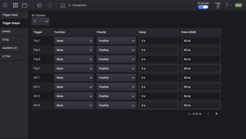
The physical trigger connectors can be used as inputs or outputs. When a trigger connector is used as an output, the following settings can be configured.
For the M9484C, routes a signal to a trigger connector for output.
| Function | Description | Availability |
|---|---|---|
| None (NONE) | No signals are routed to the connector. The connector may be an input. |
M9484C |
| Source Settled (SETTled) | Signals that the RF output is settled (frequency, phase, and amplitude are all within specification) |
M9484C |
| Event Connector (EVENt[1]|2|3) |
Monitor the signal output on one of the Event outputs. The toggle rate will be 300 MHz maximum (3.333... ns) and the resolution will be 600 MHz (1.666... ns). |
M9484C |
| Global Trigger | The global trigger signal is routed to the connector |
M9484C with Option PCH |
| Timer Trigger (TIMer) | Indication when the timer expires |
M9484C |
| Date/Time Trigger (DTIMe) | Indication when the date and time trigger occurs | M9484C |
| Logic Low (LLOW) | A logic low level |
M9484C |
| Logic High (LHIGh) | A logic high level |
M9484C |
| Trigger Clock (TCLock) | Provides the same signal used to clock the triggering system, 300 MHz. | M9484C |
| Trigger Input Connector (TRIG[1]|2|3|4|5) |
Provides the signal received on the indicated Trigger Input connector to the Trigger Output. The routing of the Trigger Input connectors to the Trigger Output connectors pass through the triggering system of the instrument, thus the resolution of the routing is 1.666 ns.
|
M9484C |
|
GUI Location |
System Menu (triple bar icon) > Connectors > Trigger Output tab > Function |
|
SCPI Command |
:ROUTe[:CONNectors][:RF<channel>]:TRIG[1]|2|3|4|5|6|7|8|9|10|11|12|13|14|15|16|17|18:OUTPut NONE|SETTled|SWEep|SRUN|EVENt[1]|2|3|GTRigger|TIMer|DTIMe|LLOW|LHIGh|TCLock|TRIG[1]|2|3|4|5 :ROUTe[:CONNectors][:RF<channel>]:TRIG[1]|2|3|4|5|6|7|8|9|10|11|12|13|14|15|16|17|18:OUTPut? |
|
SCPI Example |
ROUT:CONN:RF1:TRIG1:OUTP SETT ROUT:CONN:RF1:TRIG1:OUTP? |
|
Notes |
Attempting to send TRIG<number> for connectors that don’t exist on the instrument will generate an Execution Error When routing the signal received on a Trigger Input Connector to Trigger Output:
|
|
Couplings |
If the specified connector was being used as an input by any feature, then the trigger input type for those feature(s) is set to Trigger Key and a Settings Conflict error message is generated. |
|
Preset |
NONE |
|
State Saved |
Yes |
| Backward Compatibility SCPI |
N5182B: :ROUTe[:CONNectors]:TRIGger1|[2]:OUTPut SWEep|SRUN|SETTled|PVIDeo|PSYNc|LXI|PULSe|TRIGger2|SFDone|NONE :ROUTe[:CONNectors]:TRIGger1|[2]:OUTPut? |
|
Initial S/W Revision |
A.09.00 |
|
Modified S/W Revisions |
A.15.00 - Added support for Global Trigger, Timer, Date/Time, Logic Low, and Logic High as a selection A.16.00 - Added support for Sweep Out and Sweep Run as a selection A.16.21- Added support for Trigger Clock and routing the signals received on a Trigger Input connector to the Trigger Output . |
For the M9484C, sets the polarity of the signal output at the trigger connector.
|
GUI Location |
System Menu (triple bar icon) > Connectors > Trigger Output tab > Polarity |
|
SCPI Command |
:ROUTe[:CONNectors][:RF<channel>]:TRIG<connector>:OUTPut:POLarity POSitive|NEGative :ROUTe[:CONNectors][:RF<channel>]:TRIG<connector>:OUTPut:POLarity? |
|
SCPI Example |
ROUT:CONN:RF1:TRIG1:OUTP:POL POS ROUT:CONN:RF1:TRIG1:OUTP:POL? |
|
Notes |
Attempting to send TRIG<number> for connectors that don’t exist on the instrument will generate an Execution Error. |
|
Preset |
POSitive |
|
Range |
Negative | Positive |
|
State Saved |
Yes |
|
Initial S/W Revision |
A.09.00 |
For the M9484C, sets the output delay of a trigger connector. Its value is independent of any other delays applied to the signal being output.
|
GUI Location |
System Menu (triple bar icon) > Connectors > Trigger Output tab > Delay |
|
SCPI Command |
:ROUTe[:CONNectors][:RF<channel>]:TRIG[1]|2|3|4|5|6|7|8|9|10|11|12|13|14|15|16|17|18:OUTPut:DELay <time> :ROUTe[:CONNectors][:RF<channel>]:TRIG[1]|2|3|4|5|6|7|8|9|10|11|12|13|14|15|16|17|18:OUTPut:DELay? |
|
SCPI Example |
ROUT:CONN:RF1:TRIG1:OUTP:DEL 5 us ROUT:CONN:RF1:TRIG1:OUTP:DEL? |
|
Notes |
Attempting to send TRIG<number> for connectors that don’t exist on the instrument will generate an Execution Error. For M9484C: For Trigger Output function of Trigger Clock, DELay is not applicable. The value can be set and queried, but has no effect on the Trigger Output. |
|
Preset |
0 s |
|
State Saved |
Yes |
|
Min |
0 s |
|
Max |
For M9484C:6.825 us |
|
Resolution |
For M9484C: 1.666… ns |
|
Initial S/W Revision |
A.09.00 |
| Modified S/W Revision | A.16.21 - Added coupling for Trigger Clock |
For the M9484C, sets the minimum duration of the trigger output level, helping make sure that outputs are wide enough in time to trigger external equipment. Note: If the trigger event transitions to inactive and back to active during the initial width, that event is lost and does not extend the width.
|
GUI Location |
System Menu (triple bar icon) > Connectors > Trigger Output tab > Pulse Width |
|
SCPI Command |
:ROUTe[:CONNectors][:RF<channel>]:TRIG[1]|2|3|4|5|6|7|8|9|10|11|12|13|14|15|16|17|18:OUTPut:WIDTh <time> :ROUTe[:CONNectors][:RF<channel>]:TRIG[1]|2|3|4|5|6|7|8|9|10|11|12|13|14|15|16|17|18:OUTPut:WIDTh? |
|
SCPI Example |
ROUT:CONN:RF1:TRIG1:OUTP:WIDT 5 s ROUT:CONN:RF1:TRIG1:OUTP:WIDT? |
|
Notes |
Attempting to send TRIG<number> for connectors that don’t exist on the instrument will generate an Execution Error. For M9484C: When Trigger Output function is set to Trigger Clock, WIDTh is not applicable. The value can be set and queried, but has no effect on the Trigger Output. When Trigger Output function is set to Trigger Input Connector, WIDTh is allowed to be set to 0 which indicates to pass the Trigger Input Connector to the Trigger Output Connector. If WIDTh value is 0 when the Trigger Output function is changed to a selection other than a Trigger Input Connector, the WIDTh value is set to the preset value. |
|
Preset |
50 ns |
|
State Saved |
Yes |
|
Min |
0 when Trigger Out function is set to Trigger Input Connector Otherwise 10 ns |
|
Max |
7 s |
|
Resolution |
For M9484C: 1.666… ns to double precision |
|
Initial S/W Revision |
A.09.00 |
| Modified S/W Revision | A.16.21 - Added coupling for Trigger Clock and Trigger Input Connectors |
Supported on the M9484C.
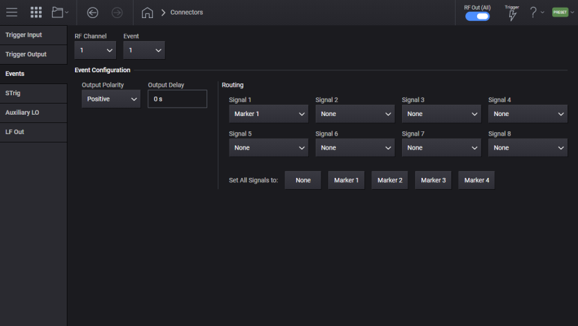
For M9484C: These three output-only connectors have precise timing (at 3 GHz) for markers on baseband signals. The maximum rate of change is 600 MHz. If an Event output is configured to change too quickly, the output will only change on 600 MHz boundaries, regaining the proper level and precise timing wherever the rate of change is 600 MHz or less.
For the M9484C, Event connector routing can output markers from one or more signals, given the following criteria:
Event connector routing can output markers from one or more signals, given the following criteria:
For each connector, only one marker can be selected from each signal.
Only per-signal marker selections for a connector can be ORed together. Note: If any are asserted, the output is asserted.
Per-signal marker selections cannot be combined with None or the single uniform Marker for all signals.
Event routing options:
None (NONE) - The connector is off.
Signal Marker Source(S<n>M<n>) - The Event output is asserted when the marker number from signal number is asserted. If more than one signal/marker combination is selected, then if any of them are asserted the connector output is asserted. Only one marker can be chosen from any one signal, so the list of marker selections is limited to the number of signals.
|
GUI Location |
System Menu (triple bar icon) > Connectors > Events tab > Routing |
|
SCPI Command |
:ROUTe[:CONNectors][:RF<channel>]:EVENt{1:3} NONE|M1|M2|M3|M4|signalMarkerSource1[,signalMarkerSource2,…[,signalMarkerSource<signalCount>]] :ROUTe[:CONNectors][:RF<channel>]:EVENt{1:3}? signalMarkerSource<n>=S1M1|S2M1|…|S8M4 |
|
SCPI Example |
ROUT:CONN:RF1:EVEN1 S1M2 ROUT:CONN:RF1:EVEN1 S1M1,S2M1,S3M2 ROUT:CONN:RF1:EVEN1? |
|
Notes |
This SCPI command is not additive; sending it clears the Event’s previous output routing and sets them only to the options contained in the command. Additive tweaking of the Event’s output routing can be done manually on the front panel display. Querying the event will return the sorted order of the list of signalMarkerSource items selected. |
|
Preset |
Event1: S1M1 Event2: S1M2 Event3: S1M3 |
|
Range |
None | Marker1 | Marker2 | Marker3 | Marker4 | Signal Marker Source<n> |
|
State Saved |
Yes |
|
Initial S/W Revision |
A.09.00 |
For the M9484C, sets the polarity of the signal output at the channel’s event connector.
|
GUI Location |
System Menu (triple bar icon) > Connectors > Events tab > Output Polarity |
|
SCPI Command |
:ROUTe[:CONNectors][:RF<channel>]:EVENt{1:3}:POLarity POSitive|NEGative :ROUTe[:CONNectors][:RF<channel>]:EVENt{1:3}:POLarity? |
|
SCPI Example |
ROUT:CONN:RF1:EVEN1:POL NEG ROUT:CONN:RF1:EVEN1:POL? |
|
Preset |
POSitive |
|
Range |
Negative | Positive |
|
State Saved |
Yes |
|
Initial S/W Revision |
A.09.00 |
For the M9484C, sets the output delay at the channel’s event connector, its value is independent of any other delays applied to the signal being output.
|
GUI Location |
System Menu (triple bar icon) > Connectors > Events tab > Output Delay |
|
SCPI Command |
:ROUTe[:CONNectors][:RF<channel>]:EVENt{1:3}:DELay timeSec :ROUTe[:CONNectors][:RF<channel>]:EVENt{1:3}:DELay? |
|
SCPI Example |
ROUT:CONN:RF1:EVEN1:DEL 50 ns ROUT:CONN:RF1:EVEN1:DEL? |
|
Preset |
0 s |
|
State Saved |
Yes |
|
Min |
0 s |
|
Max |
32.3958333333333 ns |
|
Resolution |
52.0833… ps |
|
Initial S/W Revision |
A.09.00 |
|
Modified S/W Revision |
A.10.00 Max value changed to 32.3958333333333 ns |
For M9484C - There is one STrig In connector for the instrument. STrig In is used in conjunction with Global Trigger as the External Trigger input for Global Trigger.
For M9484C, sets the input delay at the STrig In connector.
|
GUI Location |
System Menu (triple bar icon) > Connectors > > Strig > Input Delay |
|
SCPI Command |
:ROUTe[:CONNectors]:STIN:INPut:DELay <time> :ROUTe[:CONNectors]:STIN:INPut:DELay? |
|
SCPI Example |
ROUT:CONN:STIN:INP:DEL 1 US ROUT:CONN:STIN:INP:DEL? |
|
Preset |
0 s |
|
State Saved |
Yes |
|
Min |
0 s |
|
Max |
6.82 us |
|
Resolution |
For M9484C: 10 ns |
|
Initial S/W Revision |
A.10.00 |
For M9484C, sets the polarity of the signal input at the STrig In connector.
|
GUI Location |
System Menu (triple bar icon) > Connectors > > Strig > Input Slope |
|
SCPI Command |
:ROUTe[:CONNectors]:STIN:INPut:SLOPe POSitive|NEGative :ROUTe[:CONNectors]:STIN:INPut:SLOPe? |
|
SCPI Example |
ROUT:CONN:STIN:INP:SLOP NEG ROUT:CONN:STIN:INP:SLOP? |
|
Preset |
POSitive |
|
Choices |
Negative | Positive |
|
State Saved |
Yes |
|
Initial S/W Revision |
A.10.00 |
For M9484C, sets the logic level to specify the standard logic thresholds for determining digital high vs low. An input high must be at least 100 mV above the threshold and an input low must be at least 100 mV below this threshold.
|
GUI Location |
System Menu (triple bar icon) > Connectors > > Strig > Input Threshold |
|
SCPI Command |
:ROUTe[:CONNectors][:RF<channel>]:STIN:INPut:THReshold <voltage> :ROUTe[:CONNectors][:RF<channel>]:STIN:INPut:THReshold? |
|
SCPI Example |
ROUT:CONN:RF1:STIN:INP:THR 1.5 V ROUT:CONN:RF1:STIN:INP:THR? |
|
Notes |
|
|
Preset |
1.5 V |
|
State Saved |
Yes |
|
Min |
0 V |
|
Max |
3.3 V |
|
Resolution |
12.890625 mV |
|
Initial S/W Revision |
A.10.00 |
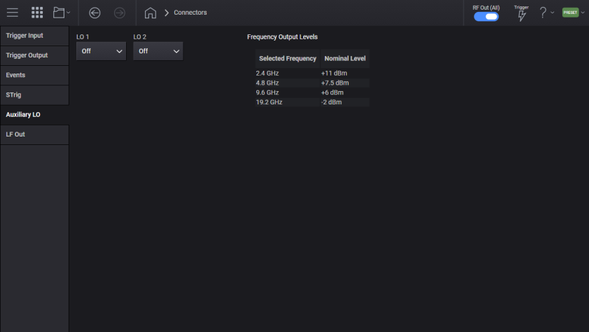
For M9484C with Option AL2.
For M9484C with Option AL2. The instrument contains two connectors labeled LO1 and LO2 for providing an Auxiliary Local Oscillator output. Each connector can be off, or provide a CW frequency of 2.4 GHz, 4.8 GHz, 9.6 GHz, or 19.2 GHz. If you are not using the output, place the setting in off to minimize emissions.
When using V3080A, the Auxiliary LO connector(s) are used for interfacing with V3080A. With a V3080A connected the auxiliary LO port is set to 9.6 GHz and not changeable. When one V3080A is connected to the instrument the LO1 will be used, if a second V3080A is connected LO2 will be used.
|
SCPI Command |
:ROUTe[:CONNectors]:ALOScillator[1]|2 OFF|F2_4|F4_8|F9_6|F19_2 :ROUTe[:CONNectors]:ALOScillator[1]|2? |
|
SCPI Example |
ROUT:ALOS2 F9_6 |
|
Notes |
If Option AL2 is not present, attempting to change ALOS raises error 703,"Feature not supported; Auxiliary LO unavailable on this instrument" |
|
Couplings |
When one or more V3080A are in use the Auxiliary LO is set to 9.6 GHz, and not changeable. For the first V3080A detected ALOS1 will be set to 9.6 GHz, when a second V3080A is detected ALOS2 will be set to 9.6 GHz. Attempting to change the Auxiliary LO with V3080A connected will raise the error "-221, Settings conflict; cannot change Auxiliary LO with V3080A connected" |
|
Preset |
If no V3080As are connected both ALSO1 and ALSO2 are OFF. If one V3080A is connected: ALOS1 is F9_6 ALOS2 is OFF If two V3080As are connected both ALSO1 and ALSO2 are F9_6. |
|
State Saved |
Yes |
|
Initial S/W Revision |
A.11.00 |
For M9484C with Option AN1 on channel 1.
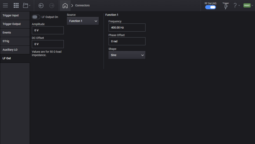
LF Out, Low Frequency Output, is a connector that provides function generator capability. This function generator is independent of the RF Output.
Enables or disables low frequency output.
|
SCPI Command |
[:SOURce][:RF<channel>]:LFOutput:STATe ON|OFF|1|0 [:SOURce][:RF<channel>]:LFOutput:STATe? |
|
SCPI Example |
LFO:STAT ON LFO:STAT? |
|
Notes |
For M9484C without Option AN1 on channel 1: Attempting to set State to ON will raise the error +703,"Feature not supported;Low Frequency Output unavailable, Option AN1 is required." |
| Couplings |
Sources cannot be enabled simultaneously on multiple modulation paths (AM/FM/ΦM path or LF output) within the same channel. Attempting to do so disables the conflicting modulation path and raises error "-221 Settings conflict; <source> cannot be enabled on multiple modulation paths on the same channel simultaneously. Disabled <conflicting output>." For
|
|
Preset |
OFF |
|
State Saved |
Yes |
| Backwards Compatibility SCPI |
E82xD, E8663D, and N51xxB: [:SOURce]:LFOutput:STATe |
|
Initial S/W Revision |
A.11.00 |
|
Modified S/W Revision |
A.15.00 - Added couplings |
Sets the source to generate the low frequency output.
|
Source Option |
Description | Availability |
|---|---|---|
| DC | Selects a DC voltage level as the LF output BNC source. |
M9484C |
| FUNCtion1 | Selects function generator 1 as the modulation source. |
M9484C |
| FUNCtion2 |
Selects function generator 2 as the modulation source. Requires Option 303 on channel 1 |
M9484C with Option 303 on channel 1 |
| DUAL |
Selects the dual function generator as the modulation source. |
M9484C with Option 303 on channel 1 |
| NOISe1 |
Selects noise generator 1 as the modulation source. |
M9484C with Option 303 on channel 1 |
| NOISe2 |
Selects noise generator 2 as the modulation source. |
M9484C with Option 303 on channel 1 |
| SWEep |
Selects swept function generator as the modulation source. |
M9484C with Option 303 on channel 1 |
| Monitor |
Selects monitoring on the LF output BNC. The source is an internal function generator in use by AM, FM, or PM. See Internal Monitor Source for selection of the function generator to monitor. |
M9484C with Option UNT on channel 1 |
|
SCPI Command |
[:SOURce][:RF<channel>]:LFOutput:SOURce DC|MONitor|FUNCtion[1]|FUNCtion2|DUAL|NOISe[1]|NOISe2|SWEep [:SOURce][:RF<channel>]:LFOutput:SOURce? |
|
SCPI Example |
LFO:SOUR DC LFO:SOUR? |
|
Notes |
For M9484C with Option AN1 and without Option 303 on channel 1: Attempting to set source to Function 2, Dual Function, Noise 1, Noise 2, or Swept Function raises the error “703, Feature not supported; <source> unavailable, option 303 is required .” For M9484C with Option AN1 and without Option UNT on channel 1: Attempting to set source to Monitor raises the error “703, Feature not supported; <source> unavailable, option UNT is required .” |
|
Preset |
For M9484C with Option AN1 and Option UNT on channel 1: MON For M9484C with Option AN1 and without Option UNT on channel 1: FUNC1 |
| Couplings |
Sources cannot be enabled simultaneously on multiple modulation paths (AM/FM/ΦM path or LF output) within the same channel. Attempting to do so disables the conflicting modulation path and raises error "-221 Settings conflict; <source> cannot be enabled on multiple modulation paths on the same channel simultaneously. Disabled conflicting output." When source is set to DC, amplitude is set to 0 and is unchangeable. Setting source to DC when amplitude is not 0 raises the error "-221, Setting conflict; LF Output Amplitude is set to 0 and is unchangeable when Source is set to DC." For
|
| Range | DC|Monitor|Function 1|Function 2|Dual Function|Noise 1|Noise 2|Swept Function |
|
State Saved |
Yes |
| Backwards Compatibility SCPI |
E82x7D, E8663D and N51xxB: [:SOURce]:LFOutput:SOURce |
| Backwards Compatibility Notes |
For E82x7D and E8663D: Alias [:SOURce]:LFOutput:SOURce INT1 to [:SOURce]:LFOutput:SOURce MON; [:SOURce]:LFOutput:SOURce:MONitor FUNCtion1 Alias [:SOURce]:LFOutput:SOURce INT2 to [:SOURce]:LFOutput:SOURce MON; [:SOURce]:LFOutput:SOURce:MONitor FUNCtion2 When [SOURce]:LFOutput:SOURce is set to INT1 or INT2, the LF Output Source is set to Monitor, and the LF Output Internal Monitor Source is set to FUNC1 or FUNC2, respectively. For reference, see Internal Monitor Source. When [:SOURce]:LFOutput:FUNCtion[1]|2:SHAPe is set to NOISe, DUALsine, or SWEPtsine, the LF Output Source will not change but comprise a Noise, Dual, or Swept Function Generator respectively. Once in this state, the LF Output source can only be restored to the true Function 1 or 2 from the given comprised function when [:SOURce]:LFOutput:FUNCtion[1]|2:SHAPe is set to SINE|TRIangle|PULSe|RAMP|SQUare. See Shape. Query will return the compatible legacy value when SCPI backward compatibility mode is set to E82x7 or E8663D, see SCPI Backward Compatibility Mode. For N51xxB: Alias [:SOURce]:LFOutput:SOURce FUNCtion to [:SOURce]:LFOutput:SOURce FUNCtion1 |
|
Initial S/W Revision |
A.11.00 |
|
Modified S/W Revision |
A.15.00 – Added backwards compatibility |
Sets the amplitude to generate low frequency output. The value is for 50 Ohm load impedance.
|
SCPI Command |
[:SOURce][:RF<channel>]:LFOutput:AMPLitude <voltage> [:SOURce][:RF<channel>]:LFOutput:AMPLitude? |
|
SCPI Example |
LFO:AMPL 2V LFO:AMPL? |
|
Preset |
0 V |
| Couplings |
When source is set to DC, amplitude is set to 0 and is unchangeable. Attempting to change amplitude to values higher or lower than allowed clips amplitude and raises the error, “-222, Data out of range; value clipped to <upper or lower> limit.” For M9484C:
|
|
State Saved |
Yes |
|
Min |
For M9484C: Current minimum = Offset – 5V |
|
Max |
For M9484C: Current maximum = 5V – Offset |
|
Resolution |
0.001 V |
| Backwards Compatibility SCPI |
E82x7D, E8663D, and N51xxB: [:SOURce]:LFOutput:AMPLitude |
|
Initial S/W Revision |
A.11.00 |
| Modified S/W Revision |
A.15.00 – Added coupling with DC offset A.16.00 – Adjusted min and max limits |
Sets the DC offset (in volts) to generate low frequency output. The value is for 50 Ohm load impedance.
|
SCPI Command |
[:SOURce][:RF<channel>]:LFOutput:OFFSet <voltage> [:SOURce][:RF<channel>]:LFOutput:OFFSet? |
|
SCPI Example |
LFO:OFFS -2V LFO:OFFS? |
|
Preset |
0 V |
| Couplings |
Attempting to change DC offset to values higher or lower than allowed clips DC offset and raises the error, “-222, Data out of range; value clipped to <upper or lower> limit.” For M9484C:
|
|
State Saved |
Yes |
|
Min |
For M9484C: Current minimum = Amplitude – 5V |
|
Max |
For M9484C: Current maximum = 5V – Amplitude |
|
Resolution |
0.001 V |
| Backwards Compatibility SCPI |
N51xxB: [:SOURce]:LFOutput:OFFSet |
|
Initial S/W Revision |
A.11.00 |
|
Modified S/W Revision |
A.15.00 - Added coupling with amplitude A.16.00 – Adjusted min and max limits |
For M9484C, load impedance is 50 Ohm and unchangeable.
|
SCPI Command |
[:SOURce][:RF<channel>]:LFOutput:LOAD:IMPedance 50|600|1000000 [:SOURce][:RF<channel>]:LFOutput:LOAD:IMPedance? |
|
SCPI Example |
LFO:LOAD:IMP 50 LFO:LOAD:IMP? |
| Notes | If the set impedance value is not 50, 600, or 1000000, the nearest valid value will be used. |
| Couplings |
When load impedance is changed, the amplitude and DC offset will be adjusted. |
|
Preset |
50 |
| Range | 50|600|1000000 |
|
State Saved |
Yes |
| Backwards Compatibility SCPI |
N51xxB: [:SOURce]:LFOutput:LOAD:IMPedance |
| Backwards Compatibility SCPI Notes | The behavior when attempting to set an invalid value differs from previous versions. |
|
Initial S/W Revision |
A.11.00 |
| Modified at S/W Revision | A.15.00 - Added backwards compatibility |
For M9484C with Option UNT on channel 1.
Sets which function generator (controlled by channel 1's AM/FM/PM) to monitor.
|
Monitor Source Option |
Description | Availability |
|---|---|---|
| Function Generator 1 (FUNCtion[1]) | Selects function generator 1 as the modulation source to monitor. |
M9484C |
| Function Generator 2 (FUNCtion2) | Selects function generator 2 as the modulation source to monitor. |
M9484C |
| Dual Function Generator (DUAL) |
Selects the dual function generator as the modulation source to monitor. |
M9484C with Option 303 and Option UNT on channel 1 |
| Sweep Function Generator (SWEep) |
Selects the sweep function generator as the modulation source. |
M9484C with Option 303 and Option UNT on channel 1 |
|
SCPI Command |
[:SOURce][:RF<channel>]:LFOutput:SOURce:MONitor FUNCtion[1]|FUNCtion2|DUAL|SWEep [:SOURce][:RF<channel>]:LFOutput:SOURce:MONitor? |
|
SCPI Example |
LFO:SOUR:MON SWE LFO:SOUR:MON? |
|
Notes |
For M9484C with Options AN1 and UNT, and without Option 303, on channel 1: Attempting to set monitor source to Dual Function or Swept Function raises the error “703, Feature not supported; <source> unavailable, option 303 is required.” When set, if the selected source is not actively in use by an AM/FM/PM modulation path on the specified channel, raises the warning, “Monitored <source> is not active.” |
|
Preset |
FUNC1 |
| Range | Function 1|Function 2|Dual Function|Swept Function |
|
Couplings |
|
|
State Saved |
Yes |
| Backwards Compatibility SCPI |
E82x7D and E8663D: [:SOURce]:LFOutput:SOURce N51xxB: [:SOURce]:LFOutput:SOURce:MONitor |
| Backwards Compatibility Notes |
For E82x7D and E8663D: Alias [:SOURce]:LFOutput:SOURce INT[1] to [:SOURce]:[:RF<channel>]:LFOutput:SOURce MON; [:SOURce]:[:RF<channel>]:LFOutput:SOURce:MONitor FUNCtion1 Alias [:SOURce]:LFOutput:SOURce INT2 to [:SOURce]:[:RF<channel>]:LFOutput:SOURce MON; [:SOURce]:[:RF<channel>]:LFOutput:SOURce:MONitor FUNCtion2 When [SOURce]:LFOutput:SOURce is set to INT1 or INT2, the LF Output Source is set to Monitor, and the LF Output Internal Monitor Source is set to FUNC1 or FUNC2, respectively. For reference, see LF Output Source. |
|
Initial S/W Revision |
A.15.00 |
For M9484C:
with Option AN1 and without Option 303 on channel 1, only Function 1 is available
with Option AN1 and Option 303 on channel 1, both Function 1 and Function 2 are available.
Sets the frequency modulation rate for the waveform on the selected function generator.
|
SCPI Command |
[:SOURce][:RF<channel>]:LFOutput:FUNCtion[1]|2:FREQuency <frequency> [:SOURce][:RF<channel>]:LFOutput:FUNCtion[1]|2:FREQuency? |
|
SCPI Example |
LFO:FUNC:FREQ 30 LFO:FUNC:FREQ? |
| Coupling | When frequency is updated, period and pulse width will be automatically adjusted to match current frequency and duty cycle values. |
|
Preset |
400 Hz |
|
State Saved |
Yes |
|
Min |
M9484C: 0.01 Hz |
|
Max |
M9484C:
|
|
Resolution |
M9484C: 0.01 Hz |
| Backwards Compatibility SCPI |
E82x7D, E8663D, and N51xxB: [:SOURce]:LFOutput:FUNCtion[1]|2:FREQuency |
|
Initial S/W Revision |
A.11.50 |
| Modified S/W/ Revision | A.15.00 - Added backwards compatibility |
Remote command only.
Sets the step increment for the frequency of the modulating signal.
|
SCPI Command |
[:SOURce][:RF<channel>]:LFOutput:FREQuency:STEP[:INCRement] <frequency> [:SOURce][:RF<channel>]:LFOutput:FREQuency:STEP[:INCRement]? |
|
SCPI Example |
LFO:FREQ:STEP 10 KHZ LFO:FREQ:STEP? |
|
Dependencies |
Default value of 500 Hz is set by Restore System Defaults |
|
Preset |
500 Hz |
|
State Saved |
Persistent, survives preset and power cycle but not saved in the instrument state. |
|
Min |
M9484C: 0.01 Hz |
|
Max |
100 MHz |
|
Resolution |
M9484C: 0.01 Hz |
|
Initial S/W Revision |
A.11.50 |
For instruments with Option 303 on channel 1, sets the phase offset (in radians) of the LF output signal. The value can be set in degrees as well.
|
SCPI Command |
[:SOURce][:RF<channel>]:LFOutput:FUNCtion[1]|2:POFFset <angle> [:SOURce][:RF<channel>]:LFOutput:FUNCtion[1]|2:POFFset? |
|
SCPI Example |
LFO:FUNC:POFF 3.14 LFO:FUNC:POFF 180 deg LFO:FUNC:POFF? |
| Notes |
For M9484C with Option AN1 and without Option 303 on channel 1: Attempting to change offset raises the error 703,”Feature not supported; LF Output Function Generator Phase Offset unavailable, option 303 is required.” Wrap the value when it exceeds the limits. |
|
Preset |
0 |
|
State Saved |
Yes |
|
Min |
-6.29 rad |
|
Max |
6.29 rad |
|
Resolution |
0.001 rad |
| Backwards Compatibility SCPI |
N51xxB: [:SOURce]:LFOutput:FUNCtion[1]|2:POFFset |
|
Initial S/W Revision |
A.11.50 |
| Modified S/W/ Revision |
A.15.00 - Added backwards compatibility A.18.00 - wrap the value when it exceeds the limits |
For instruments with Option 303 on channel 1, sets the LF output waveform shape.
|
SCPI Command |
[:SOURce][:RF<channel>]:LFOutput:FUNCtion[1]|2:SHAPe SINE|TRIangle|PULSe|RAMP|SQUare [:SOURce][:RF<channel>]:LFOutput:FUNCtion[1]|2:SHAPe? |
|
SCPI Example |
LFO:FUNC:SHAP SINE LFO:FUNC:SHAP? |
| Notes |
For M9484C with Option AN1 and without Option 303 on channel 1: Shape is Sine and unchangeable. Attempting to change shape raises the error 703,”Feature not supported; LF Output Function Generator Shape unavailable, option 303 is required.” |
|
Preset |
SINE |
|
State Saved |
Yes |
| Choices | Sine|Triangle|Pulse|Ramp |Square |
| Backwards Compatibility SCPI |
E82x7D, E8663D, and N51xxB: [:SOURce]:LFOutput:FUNCtion[1]|2:SHAPe |
| Backwards Compatibility Notes |
For E82x7D and E8663D: When NOISe, DUALsine, or SWEPtsine is selected, this command will not change the LF Output Source but comprise a Noise, Dual, or Swept Function Generator respectively. When specified source is Function 1 and shape is DUALsine, Function 1 comprises a dual function using dual function settings, apart from: • Dual Function Generator Frequency 1 will use Function Generator 1 Frequency. When specified source is Function 1 and shape is SWEPtsine, Function 1 comprises a swept function using swept function settings, apart from: • Swept Function Generator Start Frequency will use Function Generator 1 Frequency. When specified source is Function 1 and shape is NOISe, Function 1 comprises a noise generator that uses the Noise Generator 1 Type setting. When specified source is Function 2 and shape is NOISe, Function 2 comprises a noise generator that uses the Noise Generator 2 Type setting. Once shape is set to NOISe, DUALsine, or SWEPtsine, the LF Output Source can only be restored to the true Function 1 or 2 from the given, comprised function when shape is set to SINE|TRIangle|PULSe|RAMP|SQUare. |
|
Initial S/W Revision |
A.11.50 |
| Modified S/W Revision | A.15.00 - Added backwards compatibility |
For instruments with Option 303 on channel 1
Sets the ramp direction when LF output function generator shape is set to Ramp.
|
SCPI Command |
[:SOURce][:RF<channel>]:LFOutput:FUNCtion[1]|2:SHAPe:RAMP POSitive|NEGative [:SOURce][:RF<channel>]:LFOutput:FUNCtion[1]|2:SHAPe:RAMP? |
|
SCPI Example |
LFO:FUNC:SHAP:RAMP NEG LFO:FUNC:SHAP:RAMP? |
| Notes |
For M9484C with Option AN1 and without Option 303 on channel 1: Attempting to change ramp polarity raises the error 703,”Feature not supported; LF Output Function Generator Ramp Polarity unavailable, option 303 is required.” |
|
Preset |
POSitive |
| Choices | POSitive|NEGative |
|
State Saved |
Yes |
| Backwards Compatibility SCPI |
E82x7D, E8663D, and N51xxB: [:SOURce]:LFOutput:FUNCtion[1]|2:SHAPe:RAMP |
|
Initial S/W Revision |
A.11.50 |
| Modified S/W Revision | A.15.00 - Added backwards compatibility |
Sets the period when LF output function generator shape is set to Pulse.
|
SCPI Command |
[:SOURce][:RF<channel>]:LFOutput:FUNCtion[1]|2:PERiod <time> [:SOURce][:RF<channel>]:LFOutput:FUNCtion[1]|2:PERiod? |
|
SCPI Example |
LFO:FUNC:PER 1 LFO:FUNC:PER? |
|
Couplings |
When period is updated, duty cycle and frequency will be automatically adjusted to match current period and pulse width values. |
|
Preset |
2.5 ms |
|
State Saved |
Yes |
|
Min |
For M9484C:
|
|
Max |
100 s |
|
Resolution |
3.333 ns |
| Backwards Compatibility SCPI |
N51xxB: [:SOURce]:LFOutput:FUNCtion[1]|2:PERiod |
|
Initial S/W Revision |
A.15.00 |
Sets the pulse width when LF output function generator shape is set to Pulse.
|
SCPI Command |
[:SOURce][:RF<channel>]:LFOutput:FUNCtion[1]|2:PWIDth <time> [:SOURce][:RF<channel>]:LFOutput:FUNCtion[1]|2:PWIDth? |
|
SCPI Example |
LFO:FUNC:PWID 1 LFO:FUNC:PWID? |
|
Couplings |
The upper limit range value is restricted by the current value of the period. For example, if the pulse period value is set to 16 μs, the pulse width is limited to a maximum range value of 16 μs. When pulse width is updated, duty cycle will be automatically adjusted to match current period and pulse width values. |
|
Preset |
1.25 ms |
|
State Saved |
Yes |
|
Min |
3.333... ns |
|
Max |
100 s |
| Resolution |
3.333... ns |
| Backwards Compatibility SCPI |
N51xxB: [:SOURce]:LFOutput:FUNCtion[1]|2:PWIDth |
|
Initial S/W Revision |
A.15.00 |
Sets the duty cycle (in percent) when LF output function generator shape is set to Pulse.
When duty cycle is updated, period and pulse width will be automatically adjusted to match current frequency and duty cycle values.
|
SCPI Command |
[:SOURce][:RF<channel>]:LFOutput:FUNCtion[1]|2:DCYCle <real> [:SOURce][:RF<channel>]:LFOutput:FUNCtion[1]|2:DCYCle? |
|
SCPI Example |
LFO:FUNC:DCYC 20 LFO:FUNC:DCYC? |
| Couplings | When duty cycle is updated, period and pulse width will be automatically adjusted to match current frequency and duty cycle values. |
|
Preset |
50 |
|
State Saved |
Yes |
|
Min |
0 |
|
Max |
100 |
|
Resolution |
0.000000000001 |
|
Initial S/W Revision |
A.11.00 |
|
Modified S/W Revision |
A.15.00 - Added couplings |
For instruments with Option 303 on channel 1.
Sets the amplitude for the dual function generator source tones as complementary percentages of the peak analog modulation amplitude.
Setting the amplitude of one tone sets that of the other tone to make up the remaining percent.
|
SCPI Command |
[:SOURce][:RF<channel>]:LFOutput:DUAL:FUNCtion[1]|2:AMPLitude:PERCent <real> [:SOURce][:RF<channel>]:LFOutput:DUAL:FUNCtion[1]|2:AMPLitude:PERCent? |
|
SCPI Example |
LFO:DUAL:FUNC:AMPL:PERC 50 LFO:DUAL:FUNC:AMPL:PERC? |
|
Preset |
50 |
|
State Saved |
Yes |
|
Min |
0 |
|
Max |
100 |
|
Resolution |
0.1 |
|
Backwards Compatibility SCPI |
E82x7D and E8663D: [:SOURce]:LFOutput:FUNCtion[1]:FREQuency:ALTernate:AMPLitude:PERCent N51xxB: [:SOURce]:LFOutput:DUAL:FUNCtion2:AMPLitude:PERCent |
|
Backwards Compatibility Notes |
For E82x7D and E8663D: Alias [:SOURce]:LFOutput:FUNCtion[1]:FREQuency:ALTernate:AMPLitude:PERCent to [:SOURce]:LFOutput:DUAL:FUNCtion2:AMPLitude:PERCent |
|
Initial S/W Revision |
A.15.00 |
For instruments with Option 303 on channel 1.
Sets the phase offset (in radians) of dual function generator source tone 2 in relation to tone 1. Accepts degrees when provided.
|
SCPI Command |
[:SOURce][:RF<channel>]:LFOutput:DUAL:FUNCtion2:POFFset <angle> [:SOURce][:RF<channel>]:LFOutput:DUAL:FUNCtion2:POFFset? |
|
SCPI Example |
LFO:DUAL:FUNC2:POFF 2.53 LFO:DUAL:FUNC2:POFF 180 deg LFO:DUAL:FUNC2:POFF? |
| Notes | Wrap the value when it exceeds the limits. |
|
Preset |
0 |
|
State Saved |
Yes |
|
Min |
-6.29 rad |
|
Max |
6.29 rad |
|
Resolution |
0.001 |
| Backwards Compatibility SCPI |
N51xxB: [:SOURce]:LFOutput:DUAL:FUNCtion2:POFFset |
|
Initial S/W Revision |
A.15.00 |
| Modified at S/W Revision | A.18.00 - wrap the value when it exceeds the limits |
For instruments with Option 303 on channel 1.
Sets the frequency of dual function generator source tones.
|
SCPI Command |
[:SOURce][:RF<channel>]:LFOutput:DUAL:FUNCtion[1]|2:FREQuency <freq> [:SOURce][:RF<channel>]:LFOutput:DUAL:FUNCtion[1]|2:FREQuency? |
|
SCPI Example |
LFO:DUAL:FUNC:FREQ 30 LFO:DUAL:FUNC:FREQ? |
|
Preset |
400 Hz |
|
State Saved |
Yes |
|
Min |
For M9484C: 0.01 Hz |
|
Max |
For M9484C:
|
|
Resolution |
For M9484C: 0.01 Hz |
|
Backwards Compatibility SCPI |
E82x7D and E8663D: [:SOURce]:LFOutput:FUNCtion[1]:FREQuency:ALTernate N51xxB: [:SOURce]:LFOutput:DUAL:FUNCtion[1]|2:FREQuency |
|
Backwards Compatibility Notes |
E82x7D and E8663D: Alias [:SOURce]:LFOutput:FUNCtion[1]:FREQuency:ALTernate to :SOURce:LFOutput:DUAL:FUNCtion2:FREQuency |
|
Initial S/W Revision |
A.15.00 |
For instruments with Option 303 on channel1.
Sets the shape of dual function generator source tones.
|
SCPI Command |
[:SOURce][:RF<channel>]:LFOutput:DUAL:FUNCtion[1]|2:SHAPe SINE|TRIangle|PULSe|RAMP|SQUare [:SOURce][:RF<channel>]:LFOutput:DUAL:FUNCtion[1]|2:SHAPe? |
|
SCPI Example |
LFO:DUAL:FUNC:SHAP TRI LFO:DUAL:FUNC:SHAP? |
|
Preset |
SINE |
|
Range |
Sine|Triangle|Pulse|Ramp|Square |
|
State Saved |
Yes |
| Backwards Compatibility SCPI |
E82x7D and E8663D: [:SOURce]:LFOutput:FUNCtion[1]|2:SHAPe N51xxB: [:SOURce]:LFOutput:DUAL:FUNCtion[1]|2:SHAPe |
| Backwards Compatibility Notes |
For E82x7D and E8663D: Alias [:SOURce]:LFOutput:FUNCtion[1]|2:SHAPe to [:SOURce]:LFOutput:DUAL:FUNCtion[1]|2:SHAPe |
|
Initial S/W Revision |
A.15.00 |
For instruments with Option 303 on channel1.
Sets the ramp direction when LF output dual function generator shape is set to Ramp.
|
SCPI Command |
[:SOURce][:RF<channel>]:LFOutput:DUAL:FUNCtion[1]|2:SHAPe:RAMP POSitive|NEGative [:SOURce][:RF<channel>]:LFOutput:DUAL:FUNCtion[1]|2:SHAPe:RAMP? |
|
SCPI Example |
LFO:DUAL:FUNC:SHAP:RAMP POS LFO:DUAL:FUNC:SHAP:RAMP? |
|
Preset |
POSitive |
|
Range |
POSitive|NEGative |
|
State Saved |
Yes |
|
Backwards Compatibility SCPI |
E82x7D and E8663D: [:SOURce]:LFOutput:FUNCtion[1]|2:SHAPe:RAMP N51xxB: [:SOURce]:LFOutput:DUAL:FUNCtion[1]|2:SHAPe:RAMP |
|
Backwards Compatibility Notes |
For E82x7D and E8663D: Alias [:SOURce]:LFOutput:FUNCtion[1]|2:SHAPe:RAMP to [:SOURce]:LFOutput:DUAL:FUNCtion[1]|2:SHAPe:RAMP |
|
Initial S/W Revision |
A.15.00 |
For instruments with Option 303.
Sets the duty cycle (in percent) when LF output dual function generator shape is set to Pulse.
|
SCPI Command |
[:SOURce][:RF<channel>]:LFOutput:DUAL:FUNCtion[1]|2:DCYCle <real> [:SOURce][:RF<channel>]:LFOutput:DUAL:FUNCtion[1]|2:DCYCle? |
|
SCPI Example |
LFO:DUAL:FUNC:DCYC 20 LFO:DUAL:FUNC:DCYC? |
|
Preset |
50 |
|
State Saved |
Yes |
|
Min |
0 |
|
Max |
100 |
|
Resolution |
0.000000000001 |
|
Initial S/W Revision |
A.15.00 |
For instruments with Option 303 on channel1.
Sets the noise type when LF output source is set to Noise 1 or Noise 2.
|
SCPI Command |
[:SOURce][:RF<channel>]:LFOutput:NOISe[1]|2:TYPE UNIForm|GAUSsian [:SOURce][:RF<channel>]:LFOutput:NOISe[1]|2:TYPE? |
|
SCPI Example |
LFO:NOIS:TYPE GAUS LFO:NOIS:TYPE? |
|
Preset |
UNIForm |
|
Range |
Uniform|Gaussian |
|
State Saved |
Yes |
|
Backwards Compatibility SCPI |
E82x7D and E8663D: [:SOURce]:LFOutput:FUNCtion[1]|2:SHAPe:NOISe N51xxB: [:SOURce]:LFOutput:NOISe[1]|2:TYPE |
|
Backwards Compatibility Notes |
For E82x7D and E8663D: Alias [:SOURce]:LFOutput:FUNCtion[1]|2:SHAPe:NOISe to [:SOURce]:LFOutput:NOISe[1]|2:TYPE |
|
Initial S/W Revision |
A.15.00 |
For instruments with Option 303 on channel1.
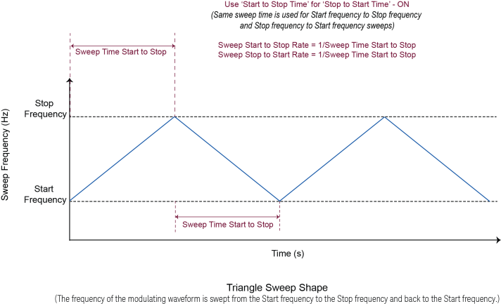
Allows the frequency of its unique, simple function generator to vary over time in a linear fashion from a start frequency to a stop frequency (and potentially back again). This sweep can be externally triggered.
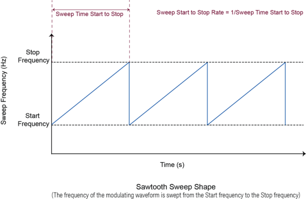
The shape in which the frequency of the modulating waveform is swept can be configured to be Sawtooth or Triangle sweep shape. These are described in Swept Function Generator - Sweep Shape.
For instruments with Option 303 on channel 1.
Sets the starting frequency for the sweep.
|
SCPI Command |
[:SOURce][:RF<channel>]:LFOutput:SWEep:FUNCtion:FREQuency:STARt <freq> [:SOURce][:RF<channel>]:LFOutput:SWEep:FUNCtion:FREQuency:STARt? |
|
SCPI Example |
LFO:SWE:FUNC:FREQ:STAR 30 Hz LFO:SWE:FUNC:FREQ:STAR? |
|
Preset |
400 Hz |
|
State Saved |
Yes |
|
Min |
For M9484C: 0.01 Hz |
|
Max |
For M9484C:
|
|
Resolution |
For M9484C: 0.01 Hz |
| Backwards Compatibility SCPI |
N51xxB: [:SOURce]:LFOutput:SWEep:FUNCtion:FREQuency:STARt |
|
Initial S/W Revision |
A.15.00 |
For instruments with Option 303 on channel 1.
Sets the stop frequency for the sweep.
|
SCPI Command |
[:SOURce][:RF<channel>]:LFOutput:SWEep:FUNCtion:FREQuency:STOP <freq> [:SOURce][:RF<channel>]:LFOutput:SWEep:FUNCtion:FREQuency:STOP? |
|
SCPI Example |
LFO:SWE:FUNC:FREQ:STOP 30 Hz LFO:SWE:FUNC:FREQ:STOP? |
|
Preset |
400 Hz |
|
State Saved |
Yes |
|
Min |
For M9484C: 0.01 Hz |
|
Max |
For M9484C:
|
|
Resolution |
For M9484C: 0.01 Hz |
|
Backwards Compatibility SCPI |
E82x7D and E8663D: [:SOURce]:LFOutput:FUNCtion[1]:FREQuency:ALTernate N51xxB: [:SOURce]:LFOutput:SWEep:FUNCtion:FREQuency:STOP |
|
Backwards Compatibility Notes |
For E82x7D and E8663D: Alias [:SOURce]:LFOutput:FUNCtion[1]:FREQuency:ALTernate to [:SOURce]:LFOutput:SWEep:FUNCtion:FREQuency:STOP |
|
Initial S/W Revision |
A.15.00 |
For instruments with Option 303 on channel 1.
Selects the waveform to be generated by the Swept Function generator.
|
SCPI Command |
[:SOURce][:RF<channel>]:LFOutput:SWEep:FUNCtion:SHAPe SINE|TRIangle|PULSe|RAMP|SQUare [:SOURce][:RF<channel>]:LFOutput:SWEep:FUNCtion:SHAPe? |
|
SCPI Example |
LFO:SWE:FUNC:SHAP SINE LFO:SWE:FUNC:SHAP? |
|
Preset |
Sine |
|
State Saved |
Yes |
|
Range |
Sine|Triangle|Pulse|Ramp|Square |
|
Initial S/W Revision |
A.15.00 |
For instruments with Option 303 on channel 1.
Sets the ramp direction when LF output swept function generator waveform shape is set to Ramp.
|
SCPI Command |
[:SOURce][:RF<channel>]:LFOutput:SWEep:FUNCtion:SHAPe:RAMP POSitive|NEGative [:SOURce][:RF<channel>]:LFOutput:SWEep:FUNCtion:SHAPe:RAMP? |
|
SCPI Example |
LFO:SWE:FUNC:SHAP:RAMP POS LFO:SWE:FUNC:SHAP:RAMP? |
|
Preset |
POSitive |
|
Range |
POSitive|NEGative |
|
State Saved |
Yes |
| Backwards Compatibility SCPI |
N51xxB: [:SOURce]:LFOutput:SWEep:FUNCtion:SHAPe:RAMP |
|
Initial S/W Revision |
A.15.00 |
For instruments with Option 303 on channel 1.
Sets the duty cycle (in percent) when LF output swept function generator shape is set to Pulse.
|
SCPI Command |
[:SOURce][:RF<channel>]:LFOutput:SWEep:FUNCtion:DCYCle <real> [:SOURce][:RF<channel>]:LFOutput:SWEep:FUNCtion:DCYCle? |
|
SCPI Example |
LFO:SWE:FUNC:DCYC 20 LFO:SWE:FUNC:DCYC? |
|
Preset |
50 |
|
State Saved |
Yes |
|
Min |
0 |
|
Max |
100 |
|
Resolution |
0.000000000001 |
|
Initial S/W Revision |
A.15.00 |
For instruments with Option 303 on channel 1.
Sets the sweep shape.
SAWTooth: Sweeps from start frequency to stop frequency.
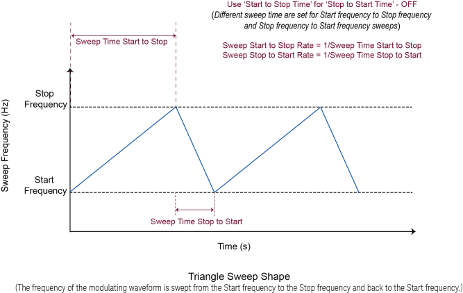
TRIangle: Sweeps from start frequency to stop frequency and back to start frequency. With a triangle shape sweep you can choose a different sweep rate for start frequency to stop frequency and another sweep rate for stop frequency to start frequency.
|
SCPI Command |
[:SOURce][:RF<channel>]:LFOutput:SWEep:SHAPe SAWTooth|TRIangle [:SOURce][:RF<channel>]:LFOutput:SWEep:SHAPe? |
|
SCPI Example |
LFO:SWE:SHAP SAWT LFO:SWE:SHAP? |
|
Preset |
SAWTooth |
|
State Saved |
Yes |
|
Range |
Sawtooth|Triangle |
| Backwards Compatibility SCPI |
N51xxB: [:SOURce]:LFOutput:SWEep:SHAPe |
|
Initial S/W Revision |
A.15.00 |
For instruments with Option 303 on channel 1.
Sets the sweep start to stop time (and implicitly sets start to stop rate) for a Sawtooth shape sweep or the first half of a Triangle shape sweep.
A Sawtooth sweep shape only sweeps from start to stop time. With Triangle shape sweep, you can choose a different sweep time for start frequency to stop frequency and another sweep time for stop frequency to start frequency.
|
SCPI Command |
[:SOURce][:RF<channel>]:LFOutput:SWEep:TIME[1] <time> [:SOURce][:RF<channel>]:LFOutput:SWEep:TIME[1]? |
|
SCPI Example |
LFO:SWE:TIME 1e-3 LFO:SWE:TIME? |
|
Preset |
1 ms |
|
State Saved |
Yes |
|
Min |
20 ns |
|
Max |
89 s |
|
Resolution |
10 ns |
| Backwards Compatibility SCPI |
N51xxB: [:SOURce]:LFOutput:SWEep:TIME[1] |
|
Initial S/W Revision |
A.15.00 |
For instruments with Option 303 on channel 1.
Sets the sweep stop to start time (and implicitly sets stop to start rate) for the second half of a triangle shape sweep.
With Triangle shape sweep, you can choose a different sweep time for start frequency to stop frequency and another sweep time for stop frequency to start frequency.
|
SCPI Command |
[:SOURce][:RF<channel>]:LFOutput:SWEep:TIME2 <time> [:SOURce][:RF<channel>]:LFOutput:SWEep:TIME2? |
|
SCPI Example |
LFO:SWE:TIME2 1 LFO:SWE:TIME2? |
|
Preset |
1 ms |
|
State Saved |
Yes |
|
Min |
20 ns |
|
Max |
89 s |
|
Resolution |
10 ns |
| Backwards Compatibility SCPI |
N51xxB: [:SOURce]:LFOutput:SWEep:TIME2 |
|
Initial S/W Revision |
A.15.00 |
For instruments with Option 303 on channel 1.
When enabled, sets 'Sweep Stop to Start Time' to 'Sweep Start to Stop Time', and couples them. Sweep Stop to Start Time (and rate) are then only settable by changing the 'Sweep Start to Stop Time'.
|
SCPI Command |
[:SOURce][:RF<channel>]:LFOutput:SWEep:TIME:COUPled ON|OFF|1|0 [:SOURce][:RF<channel>]:LFOutput:SWEep:TIME:COUPled? |
|
SCPI Example |
LFO:SWE:TIME:COUP ON LFO:SWE:TIME:COUP? |
|
Preset |
OFF |
|
State Saved |
Yes |
|
Range |
On|Off|1|0 |
| Backwards Compatibility SCPI |
N51xxB: [:SOURce]:LFOutput:SWEep:TIME:COUPled |
|
Initial S/W Revision |
A.15.00 |
For instruments with Option 303 on channel 1
Remote command only
Sets the sweep start to stop rate (and implicitly sets start to stop time) for a sawtooth shape sweep or the first half of a triangle shape sweep.
A Sawtooth sweep shape only sweeps from start to stop rate. With Triangle shape sweep, you can choose a different sweep rate for start frequency to stop frequency and another sweep rate for stop frequency to start frequency.
|
SCPI Command |
[:SOURce][:RF<channel>]:LFOutput:SWEep:RATE[1] <freq> [:SOURce][:RF<channel>]:LFOutput:SWEep:RATE[1]? |
|
SCPI Example |
LFO:SWE:RATE 1 kHz LFO:SWE:RATE? |
|
Preset |
Rate: 1 kHz Time (implicit): 1 ms |
| Dependencies | Sweep start to stop rate and time are mathematically inverse to one another. Changing one changes the other. |
|
State Saved |
Yes |
|
Min |
0.011 Hz |
|
Max |
50 MHz |
|
Resolution |
0.001 Hz |
|
Backwards Compatibility SCPI |
E82x7D and E8663D: [:SOURce]:LFOutput:FUNCtion[1]:SWEep:RATE N51xxB: [:SOURce]:LFOutput:SWEep:RATE[1] |
|
Backwards Compatibility Notes |
For E82x7D and E8663D: Alias [:SOURce]:LFOutput:FUNCtion:SWEep:RATE[1] to :SOURce:LFOutput:SWEep:RATE |
|
Initial S/W Revision |
A.15.00 |
For instruments with Option 303 on channel 1.
Remote command only
Sets the sweep stop to start rate (and implicitly sets stop to start time) for the second half of a triangle shape sweep.
With Triangle shape sweep, you can choose a different sweep rate for start frequency to stop frequency and another sweep rate for stop frequency to start frequency.
|
SCPI Command |
[:SOURce][:RF<channel>]:LFOutput:SWEep:RATE2 <freq> [:SOURce][:RF<channel>]:LFOutput:SWEep:RATE2? |
|
SCPI Example |
LFO:SWE:RATE2 1 LFO:SWE:RATE2? |
|
Preset |
1 kHz |
|
State Saved |
Yes |
|
Min |
0.011 Hz |
|
Max |
50 MHz |
|
Resolution |
0.001 Hz |
|
Backwards Compatibility SCPI |
N51xxB: [:SOURce]:LFOutput:SWEep:RATE2 |
|
Initial S/W Revision |
A.15.00 |
For instruments with Option 303 on channel 1.
Sets the choice of trigger source for triggering a sweep.
|
Trigger Source |
Description |
|---|---|
| IMMediate (Free Run) | Sweep runs continuously without pause. Update for modern triggering model. |
| KEY (Trigger Key) | Sweep runs once when the trigger key is pressed. |
| BUS | Sweep runs once per SCPI *TRG command or GET (Group Execute Trigger). |
| EXTernal |
For M9484C: Selects the use of an external trigger source. |
| Global Trigger (GTRigger) | Requires Option PCH. An error message is reported if GTRigger is selected without Option PCH. |
| Timer Trigger (TIMer) | For M9484C, Sweep is triggered at a regular time interval. |
| INTernal | Sweep is triggered by an internal Pulse Video or Pulse Sync signal. |
|
SCPI Command |
[:SOURce][:RF<channel>]:LFOutput:SWEep:TRIGger IMMediate|KEY|BUS|EXTernal|INTernal [:SOURce][:RF<channel>]:LFOutput:SWEep:TRIGger? |
|
SCPI Example |
LFO:SWE:TRIG IMM LFO:SWE:TRIG? |
|
Preset |
IMMediate |
|
Range |
Immediate|Key|Bus|External|Internal|Timer Trigger|Global Trigger |
|
State Saved |
Yes |
|
Backwards Compatibility SCPI |
E82x7D and E8663D: [SOURce]:LFOutput:FUNCtion[1]:SWEep:TRIGger N51xxB: [:SOURce]:LFOutput:SWEep:TRIGger |
|
Backwards Compatibility Notes |
For E82x7D and E8663D: Alias [SOURce]:LFOutput:FUNCtion[1]:SWEep:TRIGger to [:SOURce]:LFOutput:SWEep:TRIGger |
|
Initial S/W Revision |
A.15.00 |
For instruments with Option 303 on channel 1.
For M9484C:
Selects which rear panel connector the device uses to accept an externally applied trigger signal when external is the trigger source selection. To configure available trigger connectors, see M9484C Connectors.
|
SCPI Command |
[:SOURce][:RF<channel>]:LFOutput:SWEep:TRIGger:EXTernal:SOURce <integer> [:SOURce][:RF<channel>]:LFOutput:SWEep:TRIGger:EXTernal:SOURce? |
|
SCPI Example |
LFO:SWE:TRIG:EXT:SOUR 1 LFO:SWE:TRIG:EXT:SOUR? |
|
Preset |
1 |
|
State Saved |
Yes |
|
Min |
1 |
|
Max |
For M9484C: 18 |
| Resolution | 1 |
| Backwards Compatibility SCPI |
N51xxB: [:SOURce]:LFOutput:SWEep:TRIGger:EXTernal:SOURce |
| Backwards Compatibility Notes |
For N51xxB: For M9484C with option AN1 on channel 1: TRIGger[1] uses 1 (Trig 1) TRIGger2 uses 4 (Trig A) PULSe uses 5 (Trig B) For M9484C without option AN1 on channel 1: TRIGger[1] uses 1 (Trig 1) TRIGger2 uses 2 (Trig 2) PULSe uses 3 (Trig 3) |
|
Initial S/W Revision |
A.15.00 |
For instruments with Option 303 on channel 1.
Selects the internal trigger source.
PVIDeo: Selects Pulse Video as the internal trigger source for triggering sweep, point and function generator sweeps.
PSYNc: Selects Pulse Sync as the internal trigger source for triggering sweep, point and function generator sweeps.
|
SCPI Command |
[:SOURce][:RF<channel>]:LFOutput:SWEep:TRIGger:INTernal:SOURce PVIDeo|PSYNc [:SOURce][:RF<channel>]:LFOutput:SWEep:TRIGger:INTernal:SOURce? |
|
SCPI Example |
LFO:SWE:TRIG:INT:SOUR PVID LFO:SWE:TRIG:INT:SOUR? |
|
Preset |
PSYNc |
|
Range |
Pulse Video|Pulse Sync |
|
State Saved |
Yes |
| Backwards Compatibility SCPI |
N51xxB: [:SOURce]:LFOutput:SWEep:TRIGger:INTernal:SOURce |
|
Initial S/W Revision |
A.15.00 |
For instruments with Option 303 on channel 1.
Sets the polarity of the External trigger input connector.
|
SCPI Command |
[:SOURce][:RF<channel>]:LFOutput:SWEep:TRIGger:SLOPe POSitive|NEGative [:SOURce][:RF<channel>]:LFOutput:SWEep:TRIGger:SLOPe? |
|
SCPI Example |
LFO:SWE:TRIG:SLOP NEG LFO:SWE:TRIG:SLOP? |
|
Preset |
Positive |
|
Range |
Positive|Negative |
|
State Saved |
Yes |
| Backwards Compatibility SCPI |
N51xxB: [:SOURce]:LFOutput:SWEep:TRIGger:SLOPe |
| Backwards Compatibility Notes |
For N51xxB: This command differs from this prior behavior - Internal (PSync and PVideo) polarity is not supported. |
|
Initial S/W Revision |
A.15.00 |
For instruments with Option 303 on channel 1.
The Edit Timer Trigger button is displayed when you select Timer Trigger as the source for triggering a sweep. Clicking this button opens the Instrument Settings > Triggers and Sync > Timer Trigger tab. You can use this tab to configure the Timer Trigger Period for channels. To know more, refer to the topic Triggers and Sync.
Sets the time interval of the timer trigger source. There is only one timer trigger source for each RF channel. Therefore, the value remains the same in all trigger source selections for the channel.
|
SCPI Command |
See Timer Trigger |
|
Initial S/W Revision |
A.15.00 |
For M9484C with Option DS1
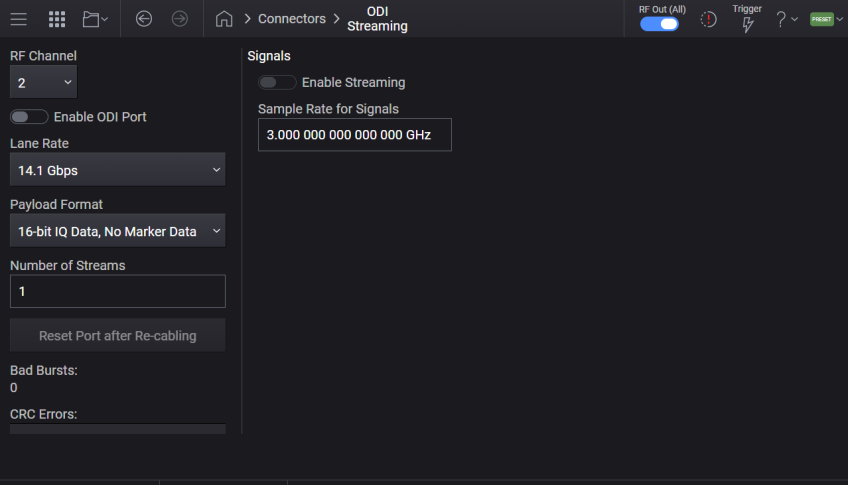
You can use the Optical Digital Interface (ODI) Streaming feature to provide the M9484C with I/Q data generated in real-time or stored in a large storage.
Step 1 - Set up the Hardware
Connect the following Keysight ODI cable to the ODI port of the channel on the front panel of your instrument.
M8121-61614 - Patch cord, ODI, F-F, 24 fiber, Type C, 3 M
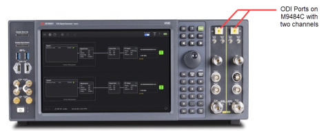
If the M9484C configuration has Option AN1 (Analog I/O), then the ODI port is not available for channel 1.
Step 2 - Configure ODI Connector settings and then Enable ODI Port for the channel. Use Connectors > ODI Streaming tab to perform this step.
Step 3 - Select the Mode as ODI Streaming for the required Signal(s) (using Signals Setup > General > Mode)
Step 4 - Configure ODI Streaming settings for the required Signal(s) (using Signals Setup > ODI Streaming tab)
Step 5 - Enable the signal(s) for which you configured the ODI Streaming mode.
The SCPI commands for the ODI Connector are described below.
Enables or disables ODI Streaming input on the specified RF Channel.
If Option AN1 is configured for channel1, then channel1 is not available for enabling ODI streaming .
|
SCPI Command |
:ROUTe[:CONNectors][:RF<channel>]:ODI[:STATe] ON|OFF|1|0 :ROUTe[:CONNectors][:RF<channel>]:ODI[:STATe]? |
|
SCPI Example |
ROUT:RF2:ODI ON ROUT:RF2:ODI? |
|
Notes |
ODI Streaming cannot be enabled on a channel using Real Time Vector Modulation or if the channel is not configured as Independent. For M9484C without option DS1, attempting to enable this setting issues 703 Feature not supported error. For M9484C with option DS1, if the channel uses Real Time Vector Modulation or is not configured as Independent, attempting to enable this setting issues -221 Settings conflict error. |
|
Preset |
OFF |
|
State Saved |
Yes |
|
Initial S/W Revision |
A.16.00 |
Sets the lane rate.
|
SCPI Command |
:ROUTe[:CONNectors][:RF<channel>]:ODI:LRATe R14G1|R12G5 :ROUTe[:CONNectors][:RF<channel>]:ODI:LRATe? |
|
SCPI Example |
ROUT:RF2:ODI:LRAT R12G5 ROUT:RF2:ODI:LRAT? |
|
Preset |
R14G1 |
|
Couplings |
Enabled when Enable Port is set to OFF. |
|
Range |
14.1 Gbps|12.5 Gbps |
|
State Saved |
Yes |
|
Initial S/W Revision |
A.16.00 |
Sets the payload format. The following VITA-49 formats are supported:
16-bit IQ Data, No Marker Data
14-bit IQ Data, 2-bit Marker Data|
24-bit IQ Data, 8-bit Marker Data
Note that VITA-49 headers and context packets are not supported.
|
SCPI Command |
:ROUTe[:CONNectors][:RF<channel>]:ODI:FORMat IQ16M0|IQ14M2|IQ24M8 :ROUTe[:CONNectors][:RF<channel>]:ODI:FORMat? |
|
SCPI Example |
ROUT:RF2:ODI:FORM IQ14M2 ROUT:RF2:ODI:FORM? |
|
Preset |
IQ16M0 |
|
Couplings |
Enabled when Enable Port is set to OFF. |
|
Options |
IQ16M0 :16-bit IQ Data, No Marker Data IQ14M2 : 14-bit IQ Data, 2-bit Marker Data IQ24M8 : 24-bit IQ Data, 8-bit Marker Data |
|
State Saved |
Yes |
|
Initial S/W Revision |
A.16.00 |
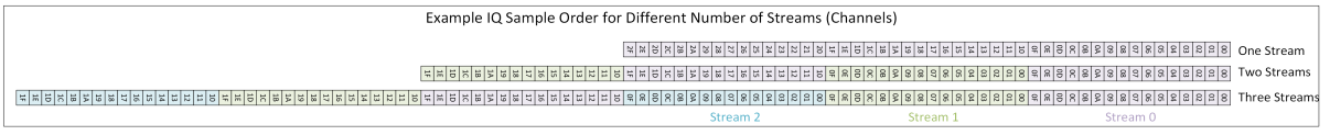
Sets the number of streams in the input ODI data.
The samples must be packed as shown in the illustration example below.
|
SCPI Command |
:ROUTe[:CONNectors][:RF<channel>]:ODI:STReam:COUNt <integer> :ROUTe[:CONNectors][:RF<channel>]:ODI:STReam:COUNt? |
|
SCPI Example |
ROUT:RF2:ODI:STR:COUN 4 ROUT:RF2:ODI:STR:COUN? |
|
Preset |
1 |
|
Couplings |
Enabled when Enable Port is set to OFF. |
|
Min |
1 |
|
Max |
8 with Option 8SG 1 without Option 8SG |
|
State Saved |
Yes |
|
Initial S/W Revision |
A.16.00 |
Resets the ODI port after reconnecting a cable.
|
SCPI Command |
:ROUTe[:CONNectors][:RF<channel>]:ODI:RESet |
|
SCPI Example |
ROUT:RF2:ODI:RES |
|
Couplings |
Enabled when the Enable Port is set to ON. |
|
State Saved |
No |
|
Initial S/W Revision |
A.16.00 |
Configures and enables signals for the ODI Connector of the specified RF channel. The Number of Streams setting determines the number of signals to be configured and enabled.
|
SCPI Command |
:ROUTe[:CONNectors][:RF<channel>]:ODI:SIGNal[:STATe] ON|OFF|1|0 :ROUTe[:CONNectors][:RF<channel>]:ODI:SIGNal[:STATe]? |
|
SCPI Example |
ROUT:RF2:ODI:SIGN ON ROUT:RF2:ODI:SIGN? |
|
Couplings |
Enabled when Enable Port is set to ON. |
|
Preset |
OFF |
|
State Saved |
No When recalling, the state is Off since ODI Streaming should be turned on after checking that the hardware is ready. |
|
Initial S/W Revision |
A.16.00 |
| Modified S/W Revision | A.16.20 - Changed State Saved from Yes to No |
Sets the sample rate of the modulating waveform, accepts frequency units (e.g., 100 MHz). The value applies to all signals whose mode is set to ODI Streaming.
|
SCPI Command |
:ROUTe[:CONNectors][:RF<channel>]:ODI:SCLock:RATE <freq> :ROUTe[:CONNectors][:RF<channel>]:ODI:SCLock:RATE? |
|
SCPI Example |
ROUT:RF2:ODI:SCL:RATE 100 MHz ROUT:RF2:ODI:SCL:RATE? |
|
Preset |
Option R25/R2E = 3.0 GHz Option R10/R1E = 1228.8 MHz Option B5X = 600 MHz Option B2X = 300 MHz Option B1X = 200 MHz |
|
State Saved |
Yes |
|
Min |
100 Hz |
|
Max |
Option R25 or R2E = 3.0 GHz Option R10 or R1E = 1228.8 MHz Option B5X = 600 MHz Option B2X = 300 MHz Option B1X = 200 MHz |
|
Resolution |
0.000001 Hz |
|
Initial S/W Revision |
A.16.00 |