This capability requires license model N7653APPC.
This topic describes the RF Output > Corrections/De-embedding screen, where you can configure and apply external corrections for your test setup.
Center Frequency Corrections Only
Channel to Channel (C2C) Corrections and Channel Flatness Refresh ![]() Setup
Setup
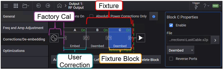
The instrument has the capability to extend the Reference Plane beyond the factory calibrated RF Output port. The Reference Plane can be extended via Corrections and/or S-parameter de-embedding.
Up to four stages of correction and de-embedding are available. These stages are referred to as blocks and are labeled as Block A, B, C, and D. For SCPI commands, block A=1, B=2, and so on.
The following table lists the available correction and de-embedding components for your test setup.
| Component | Purpose | Supported File Format(s) |
|---|---|---|
| Factory Cal |
Directly measured correction data created during the factory manufacturing process or annual calibration. |
N/A |
| Block A |
User correction data applied on top of the Factory Cal. For this block, you can:
|
.csv .uflat (for compatibility with other Keysight Technologies signal generators) |
| Block B |
De-embedding of fixtures including cables, connectors, and other passive components between the instrument and DUT to remove the effects of these test fixtures from the measurement results. Individual fixture blocks represent different fixture elements in your test setup. Calculated correction data for the sum of Blocks B, C, and/or D is applied on top of the Block A and/or Factory Cal. Prior to the software version A.14.00, only the S21 data of the fixture was used for correction. With software version A.14.00 or later, the S11 and S21 data of the fixture are used for correction. Due to this difference in the S-parameters used for correction in these software versions, the calculated correction data may vary for these software versions.
|
.s2p |
| Block C | ||
| Block D |
Enables or disables the user-flatness corrections.
|
GUI Location |
RF Output > Corrections/De-embedding > Corrections On |
|
SCPI Command |
[:SOURce][:RF<channel>]:CORRection[:STATe] ON|OFF|1|0 [:SOURce][:RF<channel>]:CORRection[:STATe]? |
|
SCPI Example |
CORR ON CORR? |
| Notes | Output power may become too high when Corrections/Deembedding fixture's S-parameter includes S21 = 0. |
|
Preset |
0 |
|
State Saved |
Yes |
|
Initial S/W Revision |
A.01.00 |
Ignores the complex response data in measured (block A) or s2p (block B, C, D) data and only applies the absolute power, phase and time corrections.
|
GUI Location |
RF Output > Corrections/De-embedding > Center Frequency Correction Only |
|
SCPI Command |
[:SOURce][:RF<channel>]:CORRection:CFConly[1]|2[:STATe] ON|OFF|0|1 [:SOURce][:RF<channel>]:CORRection:CFConly[1]|2[:STATe]? |
|
SCPI Example |
For Block A: CORR:CFC ON CORR:CFC? For Block B, C, D CORR:CFC2 ON CORR:CFC2? |
|
Preset |
0 |
|
State Saved |
Yes |
| Backwards Compatibility SCPI |
[:SOURce][:RF<channel>]:CORRection:APConly[:STATe] |
| Backwards Compatibility Notes |
Alias [:SOURce][:RF<channel>]:CORRection:APConly[:STATe] to [:SOURce][:RF<channel>]:CORRection:CFConly[1][:STATe]; [:SOURce][:RF<channel>]:CORRection:CFConly2[:STATe] |
|
Initial S/W Revision |
A.02.00 |
|
Modified S/W Revision |
A.19.01 - Changed from "applies to both measured and s2p data" to "applies to measured or s2p data". |
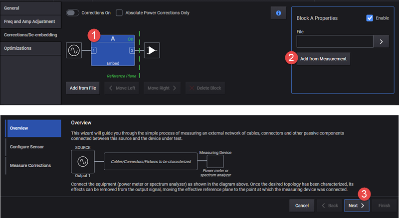
You can use the Block A properties > Add from Measurement button to access the Measure Corrections wizard. Using this wizard, you can configure and run the user correction measurement. The correction data generated from this measurement is saved to a .csv file. This file is then used as the correction file.
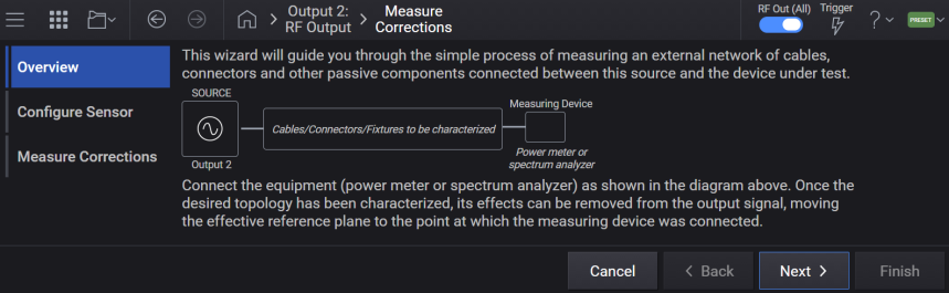
The subsections below describe the SCPI commands available to configure and run the user correction measurement.
SCPI commands defined in this section can be used to set up Correction measurements and Power Sensors used. In the user interface, these settings are included in the RF Output block's, Corrections/De-embedding block setup, when the Add from Measurement button is selected.
Supported measurement devices are as follows.
Keysight U8480 Series USB Thermocouple Power Sensor
Keysight U2000 Series USB Sensors
Including:
U2000 Series USB Power Sensors:
U8487A-CFG007
U8485A-CFG006
U2000A
U2001A
U2002A
U2004A
U2000B
U2001B
U2000H
U2001H
U2002H
U2021XA/22XA
U2041XA/42XA/43XA/44XA
U2051XA/52XA/53XA/54XA/55XA/56XA/57XA
U2061XA/62XA/63XA/64XA/65XA/66XA/67XA
X-Series Signal Analyzers:
N9000A/B
N9010A/B
N9020A/B
N9030A/B
N9040B
N9041B
M90XA
N9021B
Enables the Device List to be the sole method of specifying a Spectrum Analyzer or Power Meter to be used for Correction Measurement.
To configure external devices in the Device List, see Device List.
|
GUI Location |
RF Output > Corrections/De-embedding > Add from Measurement > Configure Sensor > Power Measurement Device > Use Device List (checkbox) |
|
SCPI Command |
[:SOURce][:RF<channel>]:CORRection:DLISt ON|OFF|1|0 [:SOURce][:RF<channel>]:CORRection:DLISt? |
|
SCPI Example |
RF3:CORR:DLIS ON RF3:CORR:DLIS? |
|
Preset |
OFF |
|
State Saved |
Yes |
|
Choices |
ON | OFF | 1 | 0 |
|
Initial S/W Revision |
A.12.00 |
Specifies a Power Meter or a Spectrum Analyzer from the Device List for user Correction Measurement. Note that the reference clock must be locked between the signal generator and Spectrum Analyzers.
To configure external devices in the Device List, see Device List.
|
GUI Location |
RF Output > Corrections/De-embedding > Add from Measurement > Configure Sensor > Power Measurement Device > Use Device List (selected) > Configure Device |
|
SCPI Command |
[:SOURce][:RF<channel>]:CORRection:DEVice <name string> [:SOURce][:RF<channel>]:CORRection:DEVice? |
|
SCPI Example |
RF3:CORR:DEV "myDevice" RF3:CORR:DEV? |
|
Notes |
If the specified device does not exist in the Device List, an error will be raised: -220,"Parameter error; Specified device does not exist" If the specified device is not a Spectrum Analyzer or Power Meter, an error will be raised: -220,"Parameter error; Correction Measurement requires a Spectrum Analyzer or Power Meter device type" |
|
Couplings |
If the device currently selected from the Device List is removed, this setting will default to NONE Value will only be utilized by hardware when Use Device List for Correction Measurement is set to ON. |
|
Preset |
NONE |
|
State Saved |
Yes |
|
Initial S/W Revision |
A.12.00 |
Selects the hardware type used in the user correction measurement when the Device List is not being used.
PMETer: Flatness calibration is done with a power meter.
SANalyzer: Flatness calibration is done with a spectrum analyzer. Note that the reference clock must be locked between the signal generator and the spectrum analyzer.
|
GUI Location |
RF Output > Corrections/De-embedding > Add from Measurement > Configure Sensor > Power Measurement Device |
|
SCPI Command |
[:SOURce][:RF<channel>]:CORRection:PMDevice PMETer|SANalyzer [:SOURce][:RF<channel>]:CORRection:PMDevice? |
|
SCPI Example |
CORR:PMD PMET CORR:PMD? |
|
Couplings |
Value will only be utilized by the instrument when Use Device List for Correction Measurement is set to OFF. |
|
Preset |
PMETer |
|
State Saved |
Yes |
|
Choices |
Power Meter | Spectrum Analyzer |
|
Initial S/W Revision |
A.01.00 |
|
Modified S/W Revision |
A.12.00 |
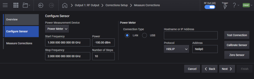
Sets the start frequency for the user flatness calibration step array.
|
GUI Location |
RF Output > Corrections/De-embedding > Add from Measurement > Start Frequency |
|
SCPI Command |
[:SOURce][:RF<channel>]:CORRection:FLATness:STEP:STARt <freq> [:SOURce][:RF<channel>]:CORRection:FLATness:STEP:STARt? |
|
SCPI Example |
CORR:FLAT:STEP:STAR 1GHz CORR:FLAT:STEP:STAR? |
|
Couplings |
Coupled to Stop Frequency. If Start Frequency goes above Stop Frequency, Stop Frequency is automatically adjusted to Start Frequency. |
|
Preset |
1 GHz |
|
State Saved |
Yes |
|
Min |
For M9484C: 9 kHz |
|
Max |
For M9484C:
|
|
Resolution |
For M9484C: 0.00001 Hz |
|
Initial S/W Revision |
A.01.00 |
|
Modified S/W Revision |
A.09.00, A.11.00 |
|
History |
Added M9484C at A.09.00 Added M9484C-AL2 and V3080A at A.11.00 |
Sets the stop frequency for the user flatness calibration step array.
|
GUI Location |
RF Output > Corrections/De-embedding > Add from Measurement > Stop Frequency |
|
SCPI Command |
[:SOURce][:RF<channel>]:CORRection:FLATness:STEP:STOP <freq> [:SOURce][:RF<channel>]:CORRection:FLATness:STEP:STOP? |
|
SCPI Example |
CORR:FLAT:STEP:STOP 1GHz CORR:FLAT:STEP:STOP? |
|
Couplings |
Coupled to Start Frequency. If Stop Frequency goes below Start Frequency, Start Frequency is automatically adjusted to Stop Frequency. |
|
Preset |
2 GHz |
|
State Saved |
Yes |
|
Min |
For M9484C: 9 kHz |
|
Max |
For M9484C:
|
|
Resolution |
For M9484C: 0.00001 Hz |
|
Initial S/W Revision |
A.01.00 |
|
Modified S/W Revision |
A.09.00, A.11.00 |
|
History |
Added M9484C at A.09.00 Added M9484C-AL2 and V3080A at A.11.00 |
Defines the number of points in the user flatness calibration step array.
|
GUI Location |
RF Output > Corrections/De-embedding > Add from Measurement > Number of Steps |
|
SCPI Command |
[:SOURce][:RF<channel>]:CORRection:FLATness:STEP:POINts <integer> [:SOURce][:RF<channel>]:CORRection:FLATness:STEP: POINts? |
|
SCPI Example |
CORR:FLAT:STEP:POIN 2 CORR:FLAT:STEP:POIN? |
|
Preset |
10 |
|
State Saved |
Yes |
|
Min |
2 |
|
Max |
10000 |
|
Initial S/W Revision |
A.01.00 |
Sets the power meter properties when Power Meter is the selected Power Measurement Device.
Sets the type of control connection for communication using the external power meter for user flatness calibration.
|
VXI11 |
Enables the power meter for VXI-11 control through the signal generator. A power meter with GPIB can be controlled through VXI-11 using a LAN-GPIB gateway. |
|
HISLip |
Enables the power meter for HiSlip control through the signal generator |
|
SOCKets |
Enables the power meter for sockets LAN control through the signal generator. |
|
USB |
Enables the power meter for USB control through the signal generator. |
|
Initial S/W Revision |
A.01.00 |
|
GUI Location |
RF Output > Corrections/De-embedding > Add from Measurement > Configure > Connection Type > LAN |
|
SCPI Command |
[:SOURce][:RF<channel>]:CORRection:PMETer:COMMunicate:TYPE SOCKets| [:SOURce][:RF<channel>]:CORRection:PMETer:COMMunicate:TYPE? |
|
SCPI Example |
CORR:PMET:COMM:TYPE SOCK CORR:PMET:COMM:TYPE? |
|
Notes |
The settings enabled by this command are not affected by a signal generator power-on, preset, or *RST. Value will only be utilized by the instrument when Use Device List for Correction Measurement is set to OFF. |
|
Preset |
SOCKets |
|
State Saved |
No |
|
Choices |
Socket |
|
Initial S/W Revision |
A.01.00 |
Sets the internet protocol (IP) address for a power meter that is controlled by the signal generator for user flatness calibration. If connecting to a GPIB power meter through a LAN-GPIB gateway, this command sets the IP address of the gateway.
|
GUI Location |
RF Output > Corrections/De-embedding > Add from Measurement > Configure > Connection Type > Connection Type LAN > Set LAN IP Address |
|
SCPI Command |
[:SOURce][:RF<channel>]:CORRection:PMETer:COMMunicate:LAN:IP <string> [:SOURce][:RF<channel>]:CORRection:PMETer:COMMunicate:LAN:IP? |
|
SCPI Example |
CORR:PMET:COMM:LAN:IP "192.168.1.5" CORR:PMET:COMM:LAN:IP? |
|
Notes |
The settings enabled by this command are not affected by signal generator power-on, preset, or *RST. Ensure that the power meter IP address is different from the signal generator address. Value will only be utilized by the instrument when Use Device List for Correction Measurement is set to OFF. |
|
State Saved |
No |
|
Initial S/W Revision |
A.01.00 |
Specifies the VXI-11 device name for a power meter that is being controlled by the signal generator for user flatness calibration. If connecting directly to the power meter, enter the name as specified on your power meter documentation. If connecting through a LAN-GPIB gateway, enter the SICL address of the power meter.
|
GUI Location |
RF Output > Corrections/De-embedding > Add from Measurement > Configure > Connection Type > LAN > Instrument (VXI-11) > Remote Name |
|
SCPI Command |
[:SOURce][:RF<channel>]:CORRection:PMETer:COMMunicate:LAN:DEVice <string> [:SOURce][:RF<channel>]:CORRection:PMETer:COMMunicate:LAN:DEVice? |
|
SCPI Example |
CORR:PMET:COMM:LAN:DEV "instr0" CORR:PMET:COMM:LAN:DEV? |
|
Notes |
The settings enabled by this command are not affected by signal generator power-on, preset, or *RST. Value will only be utilized by the instrument when Use Device List for Correction Measurement is set to OFF. |
|
Preset |
inst0 |
|
State Saved |
No |
|
Initial S/W Revision |
A.01.00 |
Specifies the HiSLIP device name for a power meter that is being controlled by the signal generator for user flatness calibration. If connecting directly to the power meter, enter the name as specified in your power meter documentation.
|
GUI Location |
RF Output > Corrections/De-embedding > Add from Measurement > Configure > Connection Type LAN > HiSLIP > Remote Name |
|
SCPI Command |
[:SOURce][:RF<channel>]:CORRection:PMETer:COMMunicate:HISLip:DEVice <string> [:SOURce][:RF<channel>]:CORRection:PMETer:COMMunicate:HISLip:DEVice? |
|
SCPI Example |
CORR:PMET:COMM:HISL:DEV "hslip1" CORR:PMET:COMM:HISL:DEV? |
|
Notes |
The settings enabled by this command are not affected by signal generator power-on, preset, or *RST. Value will only be utilized by the instrument when Use Device List for Correction Measurement is set to OFF. |
|
Preset |
hislip0 |
|
State Saved |
No |
|
Initial S/W Revision |
A.01.00 |
Selects the USB device to be used for user flatness calibration. The query returns the USB device identification.
|
GUI Location |
RF Output > Corrections/De-embedding > Add from Measurement > Configure > Connection Type USB > Device |
|
SCPI Command |
[:SOURce][:RF<channel>]:CORRection:PMETer:COMMunicate:USB:DEVice <string> [:SOURce][:RF<channel>]:CORRection:PMETer:COMMunicate:USB:DEVice? |
|
SCPI Example |
CORR:PMET:COMM:USB:DEV "instr0" CORR:PMET:COMM:USB:DEV? |
|
Notes |
The settings enabled by this command are not affected by signal generator power-on, preset, or *RST. Value will only be utilized by the instrument when Use Device List for Correction Measurement is set to OFF. |
|
State Saved |
No |
|
Initial S/W Revision |
A.01.00 |
Remote command only.
Returns a listing of all connected USB devices.
|
SCPI Command |
[:SOURce][:RF<channel>]:CORRection:PMETer:COMMunicate:USB:LIST? |
|
SCPI Example |
CORR:PMET:COMM:USB:LIST? |
|
Notes |
The settings enabled by this command are not affected by signal generator power-on, preset, or *RST. |
|
State Saved |
No |
|
Initial S/W Revision |
A.01.00 |
Sets the IP port number on the power meter that is controlled by the signal generator for users flatness calibration.
|
5025 |
Standard mode. The command enables standard mode for simple programming. |
|
5024 |
Telnet mode. The command enables the telnet SCPI service for programming. |
|
GUI Location |
RF Output > Corrections/De-embedding > Add from Measurement > Configure > Connection Type LAN > Protocol set to Socket > Port Number |
|
SCPI Command |
[:SOURce][:RF<channel>]:CORRection:PMETer:COMMunicate:LAN:PORT <integer> [:SOURce][:RF<channel>]:CORRection:PMETer:COMMunicate:LAN:PORT? |
|
SCPI Example |
CORR:PMET:COMM:LAN:PORT 5025 CORR:PMET:COMM:LAN:PORT? |
|
Notes |
The settings enabled by this command are not affected by signal generator power-on, preset, or *RST. Value will only be utilized by the instrument when Use Device List for Correction Measurement is set to OFF. |
|
Preset |
5025 |
|
State Saved |
No |
|
Initial S/W Revision |
A.01.00 |
Calibrates the connected power meter. This is an immediate action.
|
GUI Location |
RF Output > Corrections/De-embedding > Add from Measurement > Next > Calibrate Sensor |
|
SCPI Command |
[:SOURce][:RF<channel>]:CORRection:PMETer:CALibrate |
|
SCPI Example |
CORR:PMET:CAL |
|
Initial S/W Revision |
A.01.00 |
Calibrates the connected power meter from the Device List. This is an immediate action.
|
GUI Location |
RF Output > Corrections/De-embedding > Add from Measurement > Next > Use Device List (checked) > Configure Device > (select or add a device) > Calibrate Sensor |
|
SCPI Command |
[:SOURce][:RF<channel>]:CORRection:PMETer:CALibrate:DLISt <string> |
|
SCPI Example |
CORR:PMET:CAL:DLIS "myDevice" |
|
Notes |
If the specified device does not exist in the Device List, an error will be raised: -220,"Parameter error; Specified device does not exist" If the specified device is not a Power Meter, an error will be raised: -220,"Parameter error; Power Meter Calibrate Sensor requires a Power Meter device type" |
|
Initial S/W Revision |
A.12.00 |
Zeroes the connected power meter. This is an immediate action.
|
GUI Location |
RF Output > Corrections/De-embedding > Add from Measurement > Configure > Zero Sensor |
|
SCPI Command |
[:SOURce][:RF<channel>]:CORRection:PMETer:ZERO |
|
SCPI Example |
CORR:PMET:ZERO |
|
Initial S/W Revision |
A.01.00 |
Zeroes the connected power meter from the Device List. This is an immediate action.
|
GUI Location |
RF Output > Corrections/De-embedding > Add from Measurement > Next > Use Device List (checked) > Configure Device > (select or add a device) > Zero Sensor |
|
SCPI Command |
[:SOURce][:RF<channel>]:CORRection:PMETer:ZERO:DLISt <string> |
|
SCPI Example |
CORR:PMET:ZERO:DLIS "myDevice" |
|
Notes |
If the specified device does not exist in the Device List, an error will be raised: -220,"Parameter error; Specified device does not exist" If the specified device is not a Power Meter, an error will be raised: -220,"Parameter error; Power Meter Zero Sensor requires a Power Meter device type" |
|
Initial S/W Revision |
A.12.00 |
Sets the spectrum analyzer properties when Spectrum Analyzer is the selected Power Measurement Device.
Sets the type of control connection for communication with the external spectrum analyzer for user flatness calibration.
|
GUI Location |
RF Output > Corrections/De-embedding > Add from Measurement > Configure > Connection Type > LAN |
|
VXI11 |
Enables the spectrum analyzer for VXI-11 control through the signal generator. A spectrum analyzer with GPIB can be controlled through VXI-11 using a LAN-GPIB gateway. |
|
HISLip |
Enables the spectrum analyzer for HiSlip control through the signal generator. |
|
SOCKets |
Enables the spectrum analyzer for sockets LAN control through the signal generator. |
|
USB |
Enables the spectrum analyzer for USB control through the signal generator. |
|
SCPI Command |
[:SOURce][:RF<channel>]:CORRection:SANalyzer:COMMunicate:TYPE SOCKets [:SOURce][:RF<channel>]:CORRection:SANalyzer:COMMunicate:TYPE? |
|
SCPI Example |
CORR:SAN:COMM:TYPE SOCK CORR:SAN:COMM:TYPE? |
|
Notes |
The setting enabled by this command is not affected by signal generator power-on, preset, or *RST. Value will only be utilized by the instrument when Use Device List for Correction Measurement is set to OFF. |
|
Preset |
SOCKets |
|
State Saved |
No |
|
Choices |
Socket | |
|
Initial S/W Revision |
A.01.00 |
Sets the internet protocol (IP) address for a spectrum analyzer that is controlled by the signal generator for user flatness calibration. If connecting to a GPIB spectrum analyzer through a LAN-GPIB gateway, this command sets the IP address of the gateway.
|
GUI Location |
RF Output > Corrections/De-embedding > Add from Measurement > Configure > Connection Type > LAN > Hostname or IP Address |
|
SCPI Command |
[:SOURce][:RF<channel>]:CORRection:SANalyzer:COMMunicate:LAN:IP <string> [:SOURce][:RF<channel>]:CORRection:SANalyzer:COMMunicate:LAN:IP? |
|
SCPI Example |
CORR:SAN:COMM:LAN:IP "192.168.1.5" CORR:SAN:COMM:LAN:IP? |
|
Notes |
The setting enabled by this command is not affected by signal generator power-on, preset, or *RST. Ensure that the spectrum analyzer IP address is different from the signal generator address. Value will only be utilized by the instrument when Use Device List for Correction Measurement is set to OFF. |
|
State Saved |
No |
|
Initial S/W Revision |
A.01.00 |
Enter a VXI-11 device name for a spectrum analyzer that is being controlled by the signal generator for user flatness calibration. If connecting directly to the spectrum analyzer, enter the name as specified on your spectrum analyzer documentation. If connecting through a LAN-GPIB gateway, enter the SICL address of the spectrum analyzer.
|
GUI Location |
RF Output > Corrections/De-embedding > Add from Measurement > Configure > Connection Type > LAN > Instrument (VXI-11) > Remote Name |
|
SCPI Command |
[:SOURce][:RF<channel>]:CORRection:SANalyzer:COMMunicate:LAN:DEVice <string> [:SOURce][:RF<channel>]:CORRection:SANalyzer:COMMunicate:LAN:DEVice? |
|
SCPI Example |
CORR:SAN:COMM:LAN:DEV "instr0" CORR:SAN:COMM:LAN:DEV? |
|
Notes |
The setting enabled by this command is not affected by a signal generator power-on, preset, or *RST. Value will only be utilized by the instrument when Use Device List for Correction Measurement is set to OFF. |
|
Preset |
inst0 |
|
State Saved |
No |
|
Initial S/W Revision |
A.01.00 |
Enter a HiSlip device name for a spectrum analyzer that is being controlled by the signal generator for user flatness calibration. If connecting directly to the spectrum analyzer, enter the name as specified on your spectrum analyzer documentation.
|
GUI Location |
RF Output > Corrections/De-embedding > Add from Measurement > Configure > Connection Type > LAN > HiSLIP > Address |
|
SCPI Command |
[:SOURce][:RF<channel>]:CORRection:SANalyzer:COMMunicate:HISLip:DEVice <string> [:SOURce][:RF<channel>]:CORRection:SANalyzer:COMMunicate:HISLip:DEVice? |
|
SCPI Example |
CORR:SAN:COMM:HISL:DEV "instr0" CORR:SAN:COMM:HISL:DEV? |
|
Notes |
The setting enabled by this command is not affected by signal generator power-on, preset, or *RST. Value will only be utilized by the instrument when Use Device List for Correction Measurement is set to OFF. |
|
Preset |
hislip0 |
|
State Saved |
No |
|
Initial S/W Revision |
A.01.00 |
Selects the USB device to be used for user flatness calibration. The query returns the USB device identification.
|
GUI Location |
RF Output > Corrections/De-embedding > Add from Measurement > Configure > Connection Type > USB > Device |
|
SCPI Command |
[:SOURce][:RF<channel>]:CORRection:SANalyzer:COMMunicate:USB:DEVice <string> [:SOURce][:RF<channel>]:CORRection:SANalyzer:COMMunicate:USB:DEVice? |
|
SCPI Example |
CORR:SAN:COMM:USB:DEV "instr0" CORR:SAN:COMM:USB:DEV? |
|
Notes |
The setting enabled by this command is not affected by signal generator power-on, preset, or *RST. Value will only be utilized by the instrument when Use Device List for Correction Measurement is set to OFF. |
|
State Saved |
No |
|
Initial S/W Revision |
A.01.00 |
Sets the spectrum analyzer's IP port number that is controlled by the signal generator for users flatness calibration.
|
GUI Location |
RF Output > Corrections/De-embedding > Add from Measurement > Configure > Connection Type > LAN > Protocol set to Socket > Port |
|
5025 |
Standard mode. The command enables standard mode for simple programming. |
|
5024 |
Telnet mode. The command enables the telnet SCPI service for programming. |
|
SCPI Command |
[:SOURce][:RF<channel>]:CORRection:SANalyzer:COMMunicate:LAN:PORT <integer> [:SOURce][:RF<channel>]:CORRection:SANalyzer:COMMunicate:LAN:PORT? |
|
SCPI Example |
CORR:SAN:COMM:LAN:PORT 5025 CORR:SAN:COMM:LAN:PORT? |
|
Notes |
The setting enabled by this command is not affected by signal generator power-on, preset, or *RST. Value will only be utilized by the instrument when Use Device List for Correction Measurement is set to OFF. |
|
Preset |
5025 |
|
State Saved |
No |
|
Initial S/W Revision |
A.01.00 |
Remote command only.
Query only. Returns a listing of all connected USB devices.
|
SCPI Command |
[:SOURce][:RF<channel>]:CORRection:SANalyzer:COMMunicate:USB:LIST? |
|
SCPI Example |
CORR:SAN:COMM:USB:LIST? |
|
Notes |
The setting enabled by this command is not affected by signal generator power-on, preset, or *RST. |
|
State Saved |
No |
|
Initial S/W Revision |
A.01.00 |
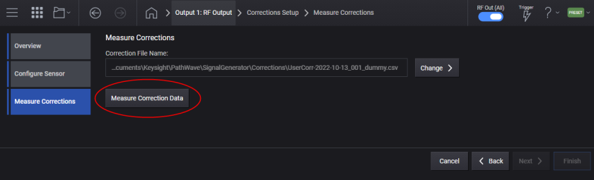
The measured correction data will be saved to the specified file. The file path can be either a full or a relative path. When a relative path is given as file path, it will be based on D:\Users\Instrument\Documents\Keysight\PathWave\SignalGenerator\Corrections. If no file is specified, a file name is automatically created.
This is an overlapped command that initiates the Correction Data measurement. The measurement can be aborted by the Abort command.
Note that the reference clock must be locked between the signal generator and the spectrum analyzer.
|
GUI Location |
RF Output > Corrections/De-embedding > Add from Measurement > Measure Corrections > Measure Correction Data |
|
SCPI Command |
[:SOURce][:RF<channel>]:CORRection:FLATness:CALibrate [<file>] |
|
SCPI Example |
CORR:FLAT:CAL |
|
State Saved |
No |
|
Initial S/W Revision |
A.01.00 |
Aborts the Correction Data measurement.
|
GUI Location |
RF Output > Corrections/De-embedding > Add from Measurement > Measure Corrections > Abort |
|
SCPI Command |
[:SOURce][:RF<channel>]:CORRection:FLATness:CALibrate:ABORt |
|
SCPI Example |
CORR:FLAT:CAL:ABOR |
|
State Saved |
No |
|
Initial S/W Revision |
A.01.00 |
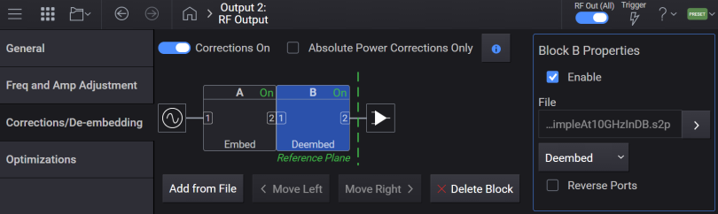
There can be up to four blocks in Corrections Setup. These blocks belong to the following two types.
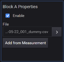
Block A - This block is for User Corrections (measured correction data). This block comes next to the instrument RF output and always exists.
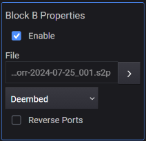
Block B, C, D - The other block type is a Fixture Block, which represents a fixture between the instrument and DUT. A Fixture Block can be dynamically configured using
To access Block Properties from the GUI, click on the applicable Block- Block A, Block B, Block C or Block D.
Displays or returns the number of Blocks configured for corrections. The maximum number of blocks is four. The minimum number is 1. The first block is for User Corrections and is always present.
|
GUI Location |
RF Output > Corrections/De-embedding |
|
SCPI Command |
[:SOURce][:RF<channel>]:CORRection:BLOCk:COUNt? |
|
SCPI Example |
CORR:BLOC:COUN? |
|
Initial S/W Revision |
A.01.00 |
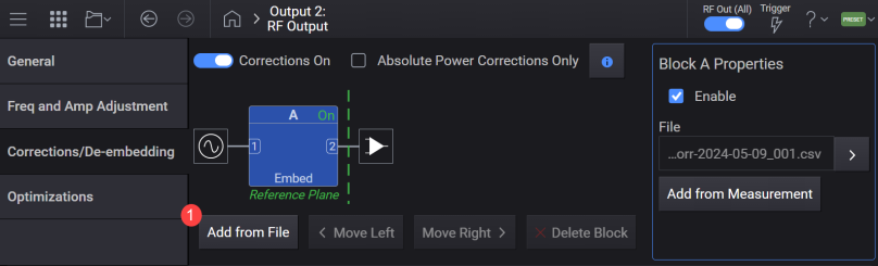
Adds a fixture block at the end of blocks.
|
GUI Location |
RF Output > Corrections/De-embedding > Add from File |
|
SCPI Command |
[:SOURce][:RF<channel>]:CORRection:BLOCk:ADD:FIXTure [<file>[,<apply>[,<rport>]]] |
|
SCPI Example |
CORR:BLOC:ADD:FIXT "data.s2p" |
| Notes |
Attempting to send a SCPI without <file> raises the error -109, "Missing parameter". <apply> and <rport> can be omitted. |
|
State Saved |
No |
|
Initial S/W Revision |
A.01.00 |
Remote command only.
Clears all the blocks except for the first one. The first block is for User Correction and cannot be deleted from the list.
|
SCPI Command |
[:SOURce][:RF<channel>]:CORRection:BLOCk:CLEar:FIXTure |
|
SCPI Example |
CORR:BLOC:CLE:FIXT |
|
Initial S/W Revision |
A.01.00 |
Deletes the specified block. If the specified block doesn’t exist, it issues an error.
There is no SCPI command for this function.
|
GUI Location |
RF Output > Corrections/De-embedding > select applicable Block > Block Properties > Delete Block |
|
Initial S/W Revision |
A.01.00 |
Moves the specified block to the specified position. If the specified block doesn’t exist, it issues an error. If the destination block is smaller than the number of blocks, it issues an error.
There is no SCPI command for this function.
|
GUI Location |
RF Output > Corrections/De-embedding > select applicable Block > Block Properties > Move Left or Move Right |
|
Initial S/W Revision |
A.01.00 |
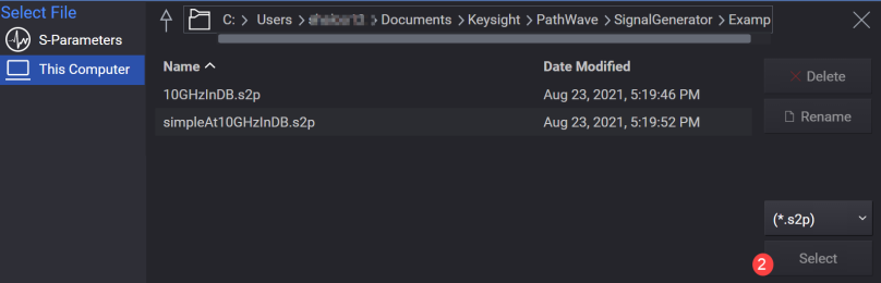
Sets or queries the correction data file (.csv or .uflat) for Block A and .s2p file for Block B, C, or D.
The default folder location is:
For M9484C:
<Documents>\Keysight\PathWave\SignalGenerator\Corrections
For Block A (1 in SCPI), the file can be a .uflat file compatible with other Keysight Technologies signal generators, or a .csv file.
The .csv file must be formatted as follows:
The first line is a header.
Each line thereafter must contain three values separated by a comma:
<Frequency in Hz>,<Amplitude in dB>,<Phase in radian>
The lines must be in increasing value of frequency; e.g. the lowest frequency in line 2, the highest frequency in the last line of the file.
For M9484C with N7653APPC subscription date of June 1, 2024 or later, the following two formats are supported for Block A .csv file:
the Frequency,Amplitude,Phase format described above
or the Frequency,Amplitude,Phase,Time format as described below
Frequency,Amplitude,Phase,Time format .csv file
The first line is a header.
Each line thereafter must contain four values separated by a comma:
<Frequency in Hz>,<Amplitude in dB>,<Phase in radian>,<Time in seconds>
The lines must be in increasing value of frequency; e.g. the lowest frequency in line 2, the highest frequency in the last line of the file.
|
GUI Location |
RF Output > Corrections/De-embedding > select applicable Block > Block Properties > Change File, current file name |
|
SCPI Command |
[:SOURce][:RF<channel>]:CORRection:BLOCk{1:4}:FILE <"file path"> [:SOURce][:RF<channel>]:CORRection:BLOCk{1:4}:FILE? |
|
SCPI Example |
CORR:BLOC:FILE "FixtureChannel2" |
|
Notes |
Attempting to load a Block A .csv file with four elements in a row, without N7653APPC of subscription date of June 1, 2024 or later, raises the error +703, Feature not supported; N7653APPC with subscription date June 1, 2024, is required. Attempting to load a Block A .csv file with four elements in a row, on an unsupported instrument will raise the error +703, Feature not supported; Correction file cannot contain four elements on {Model}. |
|
Preset |
"" |
|
State Saved |
Yes |
|
Initial S/W Revision |
A.01.00 |
|
Modified S/W Revision |
A.15.00 |
Enables or disables the selected block.
|
GUI Location |
RF Output > Corrections/De-embedding > select applicable Block > Block Properties > Enable |
|
SCPI Command |
[:SOURce][:RF<channel>]:CORRection:BLOCk{1:4}[:STATe] ON|OFF|1|0 [:SOURce][:RF<channel>]:CORRection:BLOCk{1:4}[:STATe]? |
|
SCPI Example |
CORR:BLOC 1 CORR:BLOC? |
|
State Saved |
Yes |
|
Initial S/W Revision |
A.01.00 |
Specifies how the data is applied to the cascaded correction data. When De-embed is selected, the output at the frequency point is adjusted to compensate for the amplitude and phase changes introduced by the block. When Embed is selected, it is adjusted to include them.
|
GUI Location |
RF Output > Corrections/De-embedding > Block B, C, or D > Block Properties > Deembed or Embed |
|
SCPI Command |
[:SOURce][:RF<channel>]:CORRection:BLOCk{2:4}:APPLy DEEMbedding|EMBedding |
|
SCPI Example |
CORR:BLOC2:APPL EMB CORR:BLOC2:APPL? |
|
State Saved |
Yes |
|
Choices |
De-embed | Embed |
|
Initial S/W Revision |
A.01.00 |
Specifies whether the port is reversed or not.
|
GUI Location |
RF Output > Corrections/De-embedding > Block B, C, or D > Block Properties > Reverse Ports |
|
SCPI Command |
[:SOURce][:RF<channel>]:CORRection:BLOCk{2:4}:RPORt ON|OFF|1|0 [:SOURce][:RF<channel>]:CORRection:BLOCk{2:4}:RPORt? |
|
SCPI Example |
CORR:BLOC2:RPOR 1 CORR:BLOC2:RPOR? |
|
State Saved |
Yes |
|
Initial S/W Revision |
A.01.00 |
Enables or disables Snn = 0.
When enabled, the instrument treats reflection S-parameters S11 and S22 as 0.
When disabled, S11 and S22 are normally used from the S-parameter data (no zeroing, default behavior).
|
GUI Location |
RF Output > Corrections/De-embedding > Block B, C, or D > Block Properties > Snn = 0 |
|
SCPI Command |
[:SOURce][:RF<channel>]:CORRection:BLOCk2|3|4:REFLection:ZERO ON|OFF|1|0 [:SOURce][:RF<channel>]:CORRection:BLOCk2|3|4:REFLection:ZERO? |
|
SCPI Example |
CORR:BLOC2:REFL:ZERO 1 CORR:BLOC2:REFL:ZERO? |
| Preset | OFF |
|
State Saved |
Yes |
|
Initial S/W Revision |
A.18.00 |
For M9484C, the N7653APPC subscription date of June 1, 2024 or later is required to apply specific aspects of C2C.
By extending the reference plane for flatness performance beyond the front panel to some other connection point, band breaks that exist in the hardware can be handled optimally, improving residual instrument deviations.
Channel to Channel Correction: establishes phase and time alignment between multiple channels, including across the modulation BW, for all instrument conditions, by specifying a per-path phase and time correction on an extended reference plane.
Channel Flatness Refresh: addresses the inability to adjust channel flatness via internal alignments, updating the factory calibration of the instrument via a new measurement on an external device with an extended reference plane.
For M9484C
Remote command only.
Locks the hardware in the current state. The command is expected to be used to measure correction factors in overlap regions of the hardware block diagram.
|
SCPI Command |
[:SOURce][:RF<channel>]:HARDware:LOCK ON|OFF|1|0 [:SOURce][:RF<channel>]:HARDware:LOCK? |
|
SCPI Example |
:HARD:LOCK ON :HARD:LOCK? |
|
Preset |
OFF |
|
State Saved |
Yes |
|
Initial S/W Revision |
A.15.00 |
For M9484C
Remote command only.
Locks the flatness correction at the center frequency at the current conditions.
|
SCPI Command |
[:SOURce][:RF<channel>]:HARDware:FCFValue :LOCK ON|OFF|1|0 [:SOURce][:RF<channel>]:HARDware:FCFValue:LOCK? |
|
SCPI Example |
:HARD:FCFV:LOCK ON :HARD:FCFV:LOCK? |
|
Preset |
OFF |
|
State Saved |
Yes |
|
Initial S/W Revision |
A.15.00 |
For M9484C
Remote command only.
Query only command.
Returns lower bound and upper bound frequencies for the provided PathID and dB threshold.
|
SCPI Command |
[:SOURce][:RF<channel>]:HARDware:UBANdwidth? <integer_pathId>,<float_threshold> |
|
SCPI Example |
:HARD:UBAN? 50,3.1 ! PathId=50, dB=3.1 |
| Notes | <float_threshold> is a floating point value for dB to 0.1 dB resolution. The return values are two integers of frequency with 1 Hz resolution. |
|
State Saved |
No |
|
Initial S/W Revision |
A.15.00 |
For M9484C
Remote command only.
Query only command.
Returns the PathID for the current operating point of the instrument.
|
SCPI Command |
[:SOURce][:RF<channel>]:HARDware:PATH? |
|
SCPI Example |
HARD:PATH? |
| Notes | Return value is an integer. |
|
State Saved |
No |
|
Initial S/W Revision |
A.15.00 |
For M9484C
Remote command only.
Query only command.
Returns the PathID for the provided frequency and mode. For available modes, see Optimization Mode.
|
SCPI Command |
[:SOURce][:RF<channel>]:HARDware:PATH:FMODe? <frequency>,<integer_mode> |
|
SCPI Example |
HARD:PATH:FMOD? 1000000000,2 ! 1 GHz for mode 2 |
| Notes |
<frequency> is a floating point number with mHz resolution. Units such as GHz are not permitted. Return value is an integer. |
|
State Saved |
No |
|
Initial S/W Revision |
A.15.00 |
For M9484C
Remote command only.
Query only command.
Returns an integer list of PathIDs for the provided mode. For available modes, see Optimization Mode.
|
SCPI Command |
[:SOURce][:RF<channel>]:HARDware:PATH:MODE? <integer_mode> |
|
SCPI Example |
HARD:PATH:MODE? 2 |
|
State Saved |
No |
|
Initial S/W Revision |
A.15.00 |
For M9484C
Remote command only.
Sets the value for the PathID to be used for the provided Optimization Mode when the Enable Hardware Path is set to ON.
|
SCPI Command |
[:SOURce][:RF<channel>]:HARDware:PATH:SET <integer_mode>,<integer_path> [:SOURce][:RF<channel>]:HARDware:PATH:SET? |
|
SCPI Example |
:HARD:PATH:SET 0,5 |
|
Preset |
0,0 |
|
State Saved |
Yes |
|
Initial S/W Revision |
A.15.00 |
For M9484C
Remote command only.
Enables or disables the setting of the PathID to the value entered with the Set Hardware Path command.
|
SCPI Command |
[:SOURce][:RF<channel>]:HARDware:PATH:SET:ENABle ON|OFF|1|0 [:SOURce][:RF<channel>]:HARDware:PATH:SET:ENABle? |
|
SCPI Example |
:HARD:PATH:SET:ENAB? |
|
Preset |
OFF |
|
State Saved |
Yes |
|
Initial S/W Revision |
A.15.00 |
For M9484C
Remote command only.
Query only command.
Returns a list of integers of frequencies (in Hz) where the instrument changes its internal RF hardware path or mixing products. The parameter supplied to the query refines the data retrieved by the query as listed below:
ALL = All transition points
P0 to P8 = Transition points that have PathID changes in the specified Mode (0 to 8)
PMOD = Transition points that have PathID changes in any of the modulation modes (0-4)
PCUR = Transition points that have PathID changes in the currently active mode
PALL = Transition points that have PathID changes in any of the modes
The number of entries in the list varies based on the parameter provided in the query.
|
SCPI Command |
[:SOURce][:RF<channel>]:HARDware:FREQuency:BTABle? ALL|P0|P1|P2|P3|P4|P5|P6|P7|P8|PMOD|PCUR|PALL |
|
SCPI Example |
:HARD:FREQ:BTAB? PMOD |
|
State Saved |
No |
|
Initial S/W Revision |
A.15.00 |
For M9484C
Remote command only.
Sets an added response to the existing flatness data set; referred to as the ‘field copy’ of the alignment data. The parameters to the command are:
<integer_path> = PathId obtained from Retrieve Hardware PathIDs
<IEEE Block of CSV formatted Freq,Amp,Phase> = Freq in integer Hz, dB in floating pt, Radians in floating pt. Each tuple of Freq,Amp,Phase separated with NL character
This command does not alter the factory calibration data. Performing Clear Channel Level Flatness Data Offsets will refresh the field copy of flatness from the factory calibration data. There is no query form for the command.
|
SCPI Command |
[:SOURce][:RF<channel>]:HARDware:PATH:OFData <integer_path>,<IEEE Block of CSV formatted Freq,Amp,Phase> |
|
SCPI Example |
:HARD:PATH:OFD 5,#2161000000,0.5,1.35 ! 1 MHz, 0.5 dB, 1.35 radians |
|
State Saved |
No |
|
Initial S/W Revision |
A.15.00 |
For M9484C
Remote command only.
Clears any offsets previously applied to the existing flatness data set; referred to as the ‘field copy’ of the alignment data.
This command does not alter the factory calibration data. There is no query form for the command.
|
SCPI Command |
[:SOURce][:RF<channel>]:HARDware:PATH:OFData:CLEar |
|
SCPI Example |
:HARD:PATH:OFD:CLE |
|
State Saved |
No |
|
Initial S/W Revision |
A.15.00 |
For M9484C
Remote command only.
Applies the provided time delay to the I/Q Common Delay. This delay is in addition to the I/Q Common Delay in the Adjustments Block. The value of I/Q Common Delay in the Adjustment Block is not altered by setting this hardware I/Q offset.
This command is an absolute offset, meaning setting a new value overwrites any existing value.
|
SCPI Command |
[:SOURce][:RF<channel>]:HARDware:CORRection:IQDelay <integer_path>,<value> [:SOURce][:RF<channel>]:HARDware:CORRection:IQDelay? <integer_path> |
|
SCPI Example |
:HARD:CORR:IQD 5,0.000000003 ! Offset Path ID 5 with 3 ns |
| Notes |
Value is seconds as a floating point number . |
| Min | 0 s |
| Max | 100 ns |
| Resolution | 0.01 ps |
|
Preset |
N/A |
|
State Saved |
N/A |
|
Initial S/W Revision |
A.15.00 |
For M9484C
Remote command only.
Clears any previously provided time delay to the I/Q Common Delay. This clear will occur for all PathIDs. There is no query form for the command.
|
SCPI Command |
[:SOURce][:RF<channel>]:HARDware:CORRection:IQDelay:CLEar |
|
SCPI Example |
:HARD:CORR:IQD:CLE |
|
State Saved |
No |
|
Initial S/W Revision |
A.15.00 |
For M9484C
Remote command only.
Applies the provided time delay to the Phase Accumulator . The Phase Accumulator determines the beginning time when all frequencies simultaneously have a zero phase – the origin for all frequencies phase ramps. Offsetting this time moves the coherent time origin.
This command is an absolute offset, meaning setting a new value overwrites any existing value.
|
SCPI Command |
[:SOURce][:RF<channel>]:HARDware:CORRection:PADelay <integer_path>,<value> [:SOURce][:RF<channel>]:HARDware:CORRection:PADelay? <integer_path> |
|
SCPI Example |
:HARD:CORR:PAD 5, 0.000000003 ! Offset Path ID 5 with 3 ns |
| Notes |
Value is seconds as a floating point number. |
|
Preset |
N/A |
|
State Saved |
N/A |
|
Min |
0 s |
|
Max |
100 ns |
|
Resolution |
0.01 ps |
|
Initial S/W Revision |
A.15.00 |
For M9484C
Remote command only.
Clears any previously provided time delay to apply the Phase Accumulator. This clear will occur for all PathIDs. There is no query form for the command.
|
SCPI Command |
[:SOURce][:RF<channel>]:HARDware:CORRection:PADelay:CLEar |
|
SCPI Example |
:HARD:CORR:PAD:CLE |
|
State Saved |
No |
|
Resolution |
1 mradian |
|
Initial S/W Revision |
A.15.00 |
For M9484C
Remote command only.
Applies the provided phase offset.
This command is an absolute offset, meaning setting a new value overwrites any existing value.
|
SCPI Command |
[:SOURce][:RF<channel>]:HARDware:CORRection:POFFset <path_id>,<value> [:SOURce][:RF<channel>]:HARDware:CORRection:POFFset? <path_id> |
|
SCPI Example |
:HARD:CORR:POFF 5,3 ! Offset Path ID 5 with 3 radians |
| Notes |
Value is in radians as a floating point number. |
|
Preset |
N/A |
|
State Saved |
N/A |
| Min | 0 |
| Max | 6.28 |
|
Resolution |
1 mRadian |
|
Initial S/W Revision |
A.15.00 |
For M9484C
Remote command only.
Immediate action. Clears any previously provided phase offset. This clear will occur for all PathIDs. There is no query form for the command.
|
SCPI Command |
[:SOURce][:RF<channel>]:HARDware:CORRection:POFFset:CLEar |
|
SCPI Example |
:HARD:CORR:POFF:CLE |
|
State Saved |
No |
|
Initial S/W Revision |
A.15.00 |
For M9484C
Remote command only.
Sets the delay to a channel’s baseband when two or more channels are in use and it is desired to have the basebands of each of these channels as closely aligned as possible. You can measure the offset of one channel from another, and then apply the correction to a channel with this command.
This command is an absolute offset, meaning setting a new value overwrites any existing value.
|
SCPI Command |
[:SOURce][:RF<channel>]:HARDware:CORRection:MBDelay <value> [:SOURce][:RF<channel>]:HARDware:CORRection:MBDelay? |
|
SCPI Example |
:HARD:CORR:MBD 0.000000003 ! Offset channel 1’s baseband by 3 ns |
| Notes |
Value is seconds as a floating point number . |
|
Preset |
N/A |
|
State Saved |
N/A |
|
Min |
0 |
|
Max |
10 us |
|
Resolution |
0.01 ps |
|
Initial S/W Revision |
A.15.00 |
For M9484C
Remote command only.
Clears previously provided measured baseband delay. There is no query form for the command.
|
SCPI Command |
[:SOURce][:RF<channel>]:HARDware:CORRection:MBDelay:CLEar |
|
SCPI Example |
:HARD:CORR:MBD:CLE |
|
State Saved |
No |
|
Initial S/W Revision |
A.15.00 |
For M9484C
Remote command only.
Refreshes the quiescent temperature used for phase compensation at the time the Channel to Channel (C2C) correction is performed.
This command allows you to update the quiescent temperature for amplitude. However, this update is not a prerequisite for performing the C2C correction. It's important to note that the update of the quiescent temperature for amplitude is carried out during the Alignment process. Also, it is mandatory to run the Alignment before performing the Channel to Channel correction. There is no query form for the command.
|
SCPI Command |
[:SOURce][:RF<channel>]:HARDware:UQTemp AMPLitude|PHASe |
|
SCPI Example |
:HARD:UQT PHAS |
|
State Saved |
No |
|
Initial S/W Revision |
A.15.00 |
For M9484C
Remote command only.
Query only.
Returns the fundamental frequency for the current state of the hardware.
|
SCPI Command |
[:SOURce][:RF<channel>]:HARDware:TFRequency:FUNDamental? |
|
SCPI Example |
HARD:TFR:FUND? |
|
State Saved |
No |
|
Initial S/W Revision |
A.17.00 |
For M9484C
Remote command only.
Query only.
Returns the frequency translation type for the current state of the hardware as a string value.
|
SCPI Command |
[:SOURce][:RF<channel>]:HARDware:TFRequency:TYPE? |
|
SCPI Example |
HARD:TFR:TYPE? |
|
State Saved |
No |
| Notes |
Possible return values are:
|
|
Initial S/W Revision |
A.17.00 |