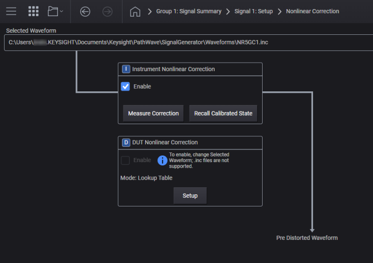
The instrument will provide one or two types of nonlinear corrections correction using Digital Predistortion (DPD) technique based on the model number. All instruments provide DUT Nonlinear Correction to predistort the signal applied to the Device Under Test, which primarily targets Power Amplifier testing. The algorithm for DUT Nonlinear Correction is compatible with the Keysight N7614C Signal Studio for Power Amplifier Test.
For M9484C, with N7653APPC subscription date of 2020.1215 or later, provides Instrument Nonlinear Correction, which compensates the instrument’s nonlinearity
This topic provides basic user-interface and SCPI descriptions. For more in-depth information, see Using Instrument Nonlinear Correction (INC).
Applying digital predistortion (DPD) to your waveform is a two-step process. You must first enable nonlinear correction and then enable vector modulation, which initiates both the DPD calculation and waveform upload operations. The IQ data is therefore modified during the upload process, creating the predistorted waveform that will reside in the signal generator's volatile (arb) memory.
Digital Predistortion (DPD) is applied to the waveform before uploading it to the arb memory. For example, when DUT Nonlinear Correction is enabled, the signal generator internally creates the predistorted waveform as a part of the waveform uploading operation. Therefore, the predistorted waveform is not saved in the non-volatile memory.
Note that the predistortion calculation doesn’t run unless Signal upload occurs. For example, the waveform is not uploaded when Enable Vector Modulation Signal is off. Which means no DPD calculation runs at this moment. When Enable Vector Modulation Signal is checked (turned on), the waveform upload is triggered and DPD is applied as a part of the upload sequence.It should also be noted that DPD cannot be applied to a waveform already in the arb memory. This is because IQ data in the arb memory cannot be modified on the signal generator.
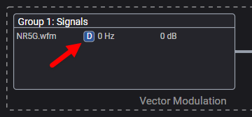
When nonlinear correction is enabled, an icon appears at the end of the Type value in the Signal Block, as shown below.
D indicates DUT nonlinear correction.
I indicates instrument nonlinear correction.
This capability requires license model N7653APPC.
Enable Instrument Nonlinear Correction
Recalling the Calibration State
Determining Calibration Completion Status
Power Calibration Maximum Iterations
Maximum Power for Power Calibration
Enable Distortion (EVM) Calibration
Distortion (EVM) Calibration Frequency Span
Distortion (EVM) Calibration Maximum Iterations
Distortion (EVM) Calibration Tolerance
Enable Equalization Calibration
Averaging Start for Distortion (EVM) Calibration
Averaging Maximum for Distortion (EVM) Calibration
Equalization Calibration Aperture
Data Extraction from INC or BND Files
This corresponds to the Enable checkbox in the Nonlinear Correction screen to enable or disable the instrument nonlinear correction. When enabled, the source will play the corrected waveform. An .inc file must be selected to enable INC. An .inc file may be chosen from the Waveform File Select, or by performing the INC calibration.
Note that this feature cannot be turned on when a waveform in the arb memory is selected, a sequence file is selected, or the Configuration is a multi-channel group.
This capability is not available in Channel Bonded configuration.
|
GUI Location |
Signals > Mode set to Waveform File, with a waveform file loaded > Configure > Measure Correction > Enable |
|
SCPI Command |
[:SOURce]:GROup<group>:SIGNal<signal>:NCORrection:INSTrument[:STATe] ON|OFF|1|0 [:SOURce]:GROup<group>:SIGNal<signal>:NCORrection:INSTrument? |
|
SCPI Example |
GRO:SIGN:NCOR:INST ON |
|
Couplings |
Cannot be turned on if the loaded waveform file is not an .inc file. Cannot be turned on if the configuration is a multi-channel group. The Enable Real-Time Instrument Nonlinear Correction setting and Enable DUT Nonlinear Correction setting are mutually exclusive. Only one can be turned on at a time. The instrument must have license model N7653APPC with support subscription date of 16-December-2020 or greater license for this command to succeed. |
|
Preset |
OFF |
|
State Saved |
Yes |
|
Range |
OFF | ON |
|
Backwards Compatibility SCPI |
The following commands are not recommended. They are for the convenience of users with existing remote programs developed for earlier versions of the signal generator or ported from a similar product. Alias [:SOURce]:SIGNal[1]:NCORrection:INSTrument[:STATe] to :SOURce:GROup1:SIGNal1:NCORrection:INSTrument[:STATe] Alias [:SOURce]:SIGNal2:NCORrection:INSTrument[:STATe] to :SOURce:GROup2:SIGNal1:NCORrection:INSTrument[:STATe] |
|
Initial S/W Revision |
A.06.00 |
|
Modified S/W Revision |
A.09.00 Added :GROup keyword A.11.50 Updated for M9484C |
See also Using Instrument Nonlinear Correction (INC).
Remote command only.
This action applies a correction from the specified
If the currently playing uncorrected waveform has characteristics which are not similar to the specified
The complimentary cumulative distribution function (CCDF) should be similar
The carrier frequency and power should be the same
The occupied bandwidth (OBW) of the calibrated waveform should be greater than or equal to the OBW of the waveform being corrected
The correction process applies the memory model polynomial generated during the calibration process to the uncorrected waveform. The fundamental requirement is that the memory model must be applicable to the waveform being corrected.
The following SCPI command applies either an INC or bonded correction:
For an INC correction, an independent group must be utilized (and only a .inc file can be used in this case),
For a bonded correction, a channel bonded group must be utilized (and only a .bnd file can be used in this case).
|
GUI Location |
Signals > Mode set to Waveform File with a *.wfm file loaded > Configure > Load Correction > select *.inc file > Confirm Correction dialog > Apply |
|
SCPI Command |
[:SOURce]:GROup<group>:SIGNal<signal>:NCORrection:INSTrument:APPLy:MMODel <inc file name> |
|
SCPI Example |
GRO:SIGN:NCOR:INST:APPL:MMOD "file_name.inc" |
|
Backwards Compatibility SCPI |
The following commands are not recommended. They are for the convenience of users with existing remote programs developed for earlier versions of the signal generator or ported from a similar product. Alias [:SOURce]:SIGNal[1]:NCORrection:INSTrument:APPLy:MMODel to Alias [:SOURce]:SIGNal2:NCORrection:INSTrument:APPLy:MMODel to |
|
Initial S/W Revision |
A.06.00 – Only supports correction using .inc files |
|
Modified S/W Revision |
A.09.00 Added :GROup keyword A.10.00 – Supports corrections using either .inc or .bnd files (when applied to the appropriate type of group). |
This action, provided an .inc file has been selected, will restore the source to the same state that existing when the calibration completed. This will result in the highest fidelity signal characteristics when playing a corrected waveform.
Note that an .inc waveform file can be selected using the same SCPI commands for selecting any waveform file, the .inc file format is supported as a standard waveform file type. However, in order to utilize an .inc waveform file, the appropriate licenses must exist.
|
GUI Location |
Signals > Mode set to Waveform File with an *.inc file loaded > Configure > Recall Calibrated State |
|
SCPI Command |
[:SOURce]:GROup<group>:SIGNal<signal>:NCORrection:INSTrument:STATe:RECall |
|
SCPI Example |
GRO:SIGN:NCOR:INST:STAT:REC |
|
Backwards Compatibility SCPI |
The following commands are not recommended. They are for the convenience of users with existing remote programs developed for earlier versions of the signal generator or ported from a similar product. Alias [:SOURce]:SIGNal[1]:NCORrection:INSTrument:STATe:RECall to Alias [:SOURce]:SIGNal2:NCORrection:INSTrument:STATe:RECall to |
|
Initial S/W Revision |
A.06.00 |
|
Modified S/W Revision |
A.09.00 Added :GROup keyword |
This button opens a screen where you can access the following setup grids and actions:
Determining Calibration Completion Status
The settings under this tab enable you to configure and test connectivity to the receiver.
See also: Supported Receivers
Enables the Device List to be the sole method of specifying a Spectrum Analyzer or Power Meter to be used for INC Calibrations.
To configure external devices in the Device List, see Device List.
|
GUI Location |
Signals > Mode set to Waveform File, with a waveform file loaded > Configure > Measure Correction > Receiver (tab) > Use Device List (checkbox) |
|
SCPI Command |
:SYSTem:COMMunicate:INCorrection:DLISt ON|OFF|1|0 :SYSTem:COMMunicate:INCorrection:DLISt? |
|
SCPI Example |
SYST:COMM:INC:DLIS ON |
|
Preset |
OFF |
|
State Saved |
Yes |
|
Choices |
ON | OFF | 1 | 0 |
|
Initial S/W Revision |
A.12.00 |
Specifies a Spectrum Analyzer from the Device List to be used for INC Calibrations.
To configure external devices in the Device List, see Device List.
|
GUI Location |
Signals > Mode set to Waveform File, with a waveform file loaded > Configure > Measure Correction > Receiver (tab) > Use Device List (selected) > Configure Device |
|
SCPI Command |
:SYSTem:COMMunicate:INCorrection:DEVice <name string> :SYSTem:COMMunicate:INCorrection:DEVice? |
|
SCPI Example |
SYST:COMM:INC:DEV "mySpectumAnalyzer" |
|
Notes |
If the specified device does not exist in the Device List, an error will be raised: -220,"Parameter error; Specified device does not exist" If the specified device is not a Spectrum Analyzer, an error will be raised: -220,"Parameter error; INC calibration requires a Spectrum Analyzer device type" |
|
Couplings |
If the device currently selected from the Device List is removed, this setting will default to NONE. Value will only be utilized by hardware when Use Device List for INC Calibration is set to ON. |
|
Preset |
NONE |
|
State Saved |
Yes |
|
Initial S/W Revision |
A.12.00 |
This configures the full VISA address of the receiver to use for the INC Calibration and/or Auto Configure Analyzer when the Device List is not being used for those features.
|
GUI Location |
Signals > Mode set to Waveform File, with a waveform file loaded > Configure > Measure Correction > Receiver (tab) > LAN (radio button) |
|
SCPI Command |
:SYSTem:COMMunicate:REMote:ADDRess <string> :SYSTem:COMMunicate:REMote:ADDRess? |
|
SCPI Example |
SYST:COMM:REM:ADDR TCPIP0::10.0.0.1::hislip0::INSTR" |
|
Couplings |
Value will only be utilized-for INC Calibration by hardware when Use Device List for INC Calibration is set to OFF. Value will only be utilized- for Auto Configure Analyzer by hardware when Use Device List for Auto Configure Analyzer is set to OFF. |
|
Preset |
This is unaffected by a Preset but is set to an empty string on a "Restore System Settings to Default Values" |
|
State Saved |
Persistent, survives preset and power cycle but not saved in the instrument state. |
|
Initial S/W Revision |
A.06.00 |
|
Modified S/W Revision |
A.12.00 |
This action begins either an instrument nonlinear correction (INC) or the channel bonding process, depending on the configuration of the specified group:
If the specified group is an independent configuration, then an INC will be performed.
If the specified group is a channel-bonded configuration, then the bonding process will be performed.
This is not an overlapped operation, the command will return when the calibration has completed, which could take a significant amount of time. A successfully completed calibration results in the following:
An *.inc or *.bnd file will exist with the same name as the uncorrected waveform file but with the appropriate extension.
The source will have the new file selected, instead of the original uncorrected waveform file.
The corrected or bonded waveform will be playing.
Various source settings will be updated depending upon the calibration combinations which were selected.
Some source features are incompatible with the calibration process or are not supported in conjunction with the calibration. Additionally, some settings will be modified by the calibration process. The calibration process will turn-off incompatible and unsupported features. At the completion of the calibration process, the state of the instrument should be inspected to determine if any desired features need to be re-configured. The following is a partial list of key settings and features which may be affected by the calibration:
Waveform settings: IQ data, number of samples, marker data, sample rate, rms, OBW, etc.
Vector modulation enabled and configured to utilize waveform IQ data only
All other modulation features are turned off (or inaccessible for bonding)
Correction and De-embedding are turned off (or inaccessible for bonding)
|
GUI Location |
Signals > Mode set to Waveform File, with a waveform file loaded > Configure > Measure Correction > Start Calibration |
|
SCPI Command |
[:SOURce]:GROup<group>:SIGNal<signal>:NCORrection:INSTrument:RUN |
|
SCPI Example |
GRO:SIGN:NCOR:INST:RUN |
|
Couplings |
This will generate appropriate errors if the following conditions exist:
|
|
Notes |
GRO:SIGN:NCOR:INST:RUN can take a significant amount of time to complete depending on the calibrations performed, the waveform properties, and the settings within the calibration. Test software will need to set the timeout appropriately or handle timeout errors (e.g. 5 minutes for Power calibration, 10 minutes for ACP calibration for span of 98.28 MHz with default iteration and tolerance). |
|
Backwards Compatibility SCPI |
The following commands are not recommended. They are for the convenience of users with existing remote programs developed for earlier versions of the signal generator or ported from a similar product. Alias [:SOURce]:SIGNal[1]:NCORrection:INSTrument:RUN to Alias [:SOURce]:SIGNal2:NCORrection:INSTrument:RUN to |
|
Initial S/W Revision |
A.06.00 |
|
Modified S/W Revision |
A.09.00 Added :GROup keyword |
See also, Using Instrument Nonlinear Correction (INC)
See also, Using a Bonded Configuration
Remote command only.
This query can be used to determine the success or failure of the last calibration process.
|
SCPI Command |
[:SOURce]:GROup<group>:SIGNal<signal>:NCORrection:INSTrument:RESult? |
|
SCPI Example |
GRO:SIGN:NCOR:INST:RES? |
|
Notes |
A result of 1 indicates success, 0 indicates no prior calibration has been performed or a failure |
|
Backwards Compatibility SCPI |
The following commands are not recommended. They are for the convenience of users with existing remote programs developed for earlier versions of the signal generator or ported from a similar product. Alias [:SOURce]:SIGNal[1]:NCORrection:INSTrument:RESult? to Alias [:SOURce]:SIGNal2:NCORrection:INSTrument:RESult? to |
|
Initial S/W Revision |
A.06.00 |
|
Modified S/W Revision |
A.09.00 Added :GROup keyword |
The settings under this tab enable you to optimize your calibration.
The calibration can be configured to perform Power, Distortion (EVM), Equalization, and ACP optimizations. Each of these calibration types have settings that can be tailored to the optimization of the instrument.
This corresponds to the Power calibration checkbox in the INC Calibration screen, Calibration tab, and will enable or disable the power calibration during the INC calibration process. Power calibration will iteratively adjust the source power and measured it via the receiver, until the difference between the desired power and the measured power is less then the specified Power Calibration Tolerance, or the maximum number of iterations are reached.
Power calibration will move the reference plane of the instrument’s output power to the input of the receiver. The default setting of Power calibration is Off so you can make the intentional decision to move the reference plane to the end of the cabling you are using for the calibration.
Power calibration will change the RF Output Power of the group (either Independent or Bonded). In the case of Bonding, the adjustment to the RF Power can be a +3 dB increase, or more, in order to compensate for the loss thru the combiner plus cables.
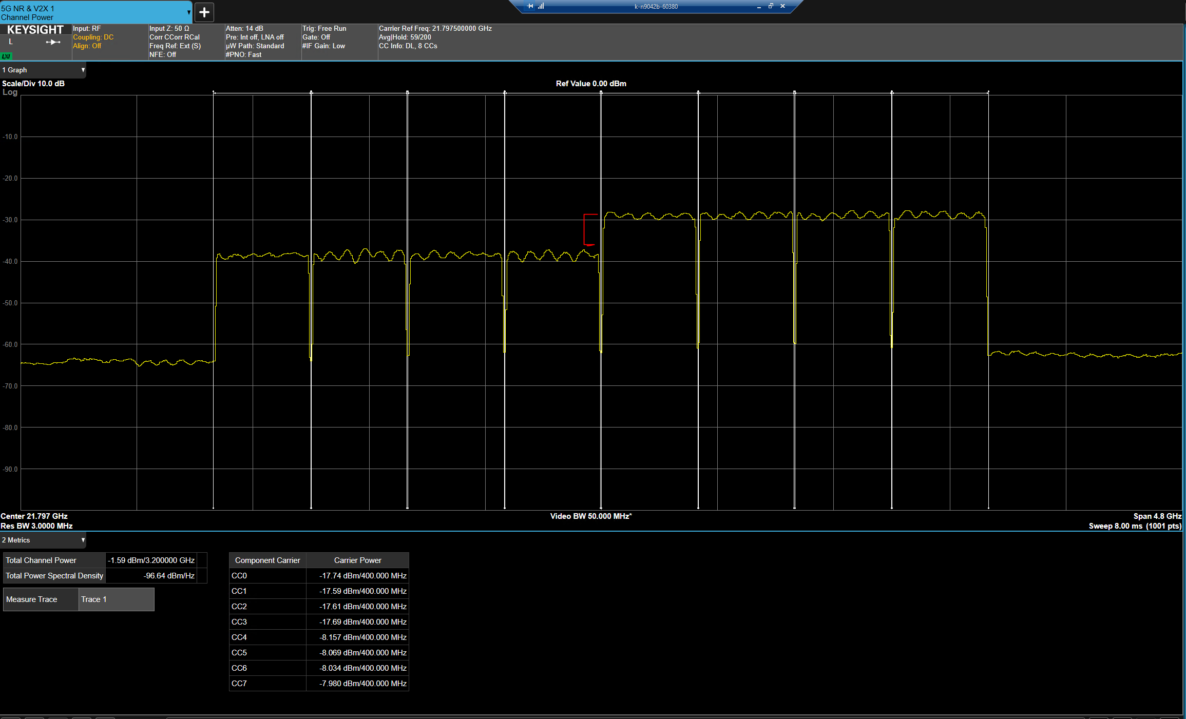
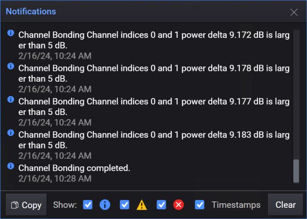
When Power Calibration is enabled for Channel Bonding you observe a ![]() significant step in amplitude at the bonding frequency, this indicates that only one of the channels can provide the requested power level. You may also receive a
significant step in amplitude at the bonding frequency, this indicates that only one of the channels can provide the requested power level. You may also receive a ![]() notification of this condition. Check the connectors and cabling between the RF output of the lower-power channel and the combiner.
notification of this condition. Check the connectors and cabling between the RF output of the lower-power channel and the combiner.
|
GUI Location |
Signals > Mode set to Waveform File, with a waveform file loaded > Configure > Measure Correction > Calibrations (tab) > Power |
|
SCPI Command |
[:SOURce]:GROup<group>:SIGNal<signal>:NCORrection:INSTrument:POWer[:STATe] ON|OFF|1|0 [:SOURce]:GROup<group>:SIGNal<signal>:NCORrection:INSTrument:POWer[:STATe]? |
|
SCPI Example |
GRO:SIGN:NCOR:INST:POW ON |
|
Couplings |
The Span setting for Power calibration is shared with Distortion (EVM), thus if the span for Distortion (EVM) is changed the span for Power is changed. |
|
Preset |
OFF |
|
State Saved |
Yes |
|
Range |
OFF | ON |
|
Backwards Compatibility SCPI |
The following commands are not recommended. They are for the convenience of users with existing remote programs developed for earlier versions of the signal generator or ported from a similar product. Alias [:SOURce]:SIGNal[1]:NCORrection:INSTrument:POWer[:STATe] to Alias [:SOURce]:SIGNal2:NCORrection:INSTrument:POWer[:STATe] to |
|
Initial S/W Revision |
A.06.00 |
|
Modified S/W Revision |
A.09.00 Added :GROup keyword |
This specifies the acceptable deviation between the power level measured by the receiver and the desired source output power level during the Power Calibration. The power calibration will iterate, adjusting the output power and measuring the power using the receiver until power difference is less than or equal to the specified tolerance or until the maximum number of iterations has been reached.
|
GUI Location |
Signals > Mode set to Waveform File, with a waveform file loaded > Configure > Measure Correction > Calibrations (tab) > Power > Tolerance |
|
SCPI Command |
[:SOURce]:GROup<group>:SIGNal<signal>:NCORrection:INSTrument:POWer:TOLerance <rel_ampl> [:SOURce]:GROup<group>:SIGNal<signal>:NCORrection:INSTrument:POWer:TOLerance? |
|
SCPI Example |
GRO:SIGN:NCOR:INST:POW:TOL 0.1 |
|
Preset |
0.1 |
|
Min |
0.1 |
|
Max |
10.0 |
|
Resolution |
0.01 |
|
State Saved |
Yes |
|
Backwards Compatibility SCPI |
The following commands are not recommended. They are for the convenience of users with existing remote programs developed for earlier versions of the signal generator or ported from a similar product. Alias [:SOURce]:SIGNal[1]:NCORrection:INSTrument:POWer:TOLerance to Alias [:SOURce]:SIGNal2:NCORrection:INSTrument:POWer:TOLerance to |
|
Initial S/W Revision |
A.06.00 |
|
Modified S/W Revision |
A.09.00 Added :GROup keyword |
This specifies the maximum number of iterations for achieving the desired power level for the power calibration. The power calibration will iterate, adjusting the output power and measuring the power using the receiver until power difference is less than or equal to the specified tolerance or until the maximum number of iterations has been reached.
|
GUI Location |
Signals > Mode set to Waveform File, with a waveform file loaded > Configure > Measure Correction > Calibrations (tab) > Power > Max Iterations |
|
SCPI Command |
[:SOURce]:GROup<group>:SIGNal<signal>:NCORrection:INSTrument:POWer:ITERations <integer> [:SOURce]:GROup<group>:SIGNal<signal>:NCORrection:INSTrument:POWer:ITERations? |
|
SCPI Example |
GRO:SIGN:NCOR:INST:POW:ITER 3 |
|
Preset |
3 |
|
Min |
1 |
|
Max |
1000 |
|
Resolution |
1 |
|
State Saved |
Yes |
|
Backwards Compatibility SCPI |
The following commands are not recommended. They are for the convenience of users with existing remote programs developed for earlier versions of the signal generator or ported from a similar product. Alias [:SOURce]:SIGNal[1]:NCORrection:INSTrument:POWer:ITERations to Alias [:SOURce]:SIGNal2:NCORrection:INSTrument:POWer:ITERations to |
|
Initial S/W Revision |
A.06.00 |
|
Modified S/W Revision |
A.09.00 Added :GROup keyword |
This specifies the maximum power value to which the Power calibration will set the source. This value corresponds to the Failsafe Max Power setting in the Advanced tab of the Instrument Nonlinear Calibration screen.
|
GUI Location |
Signals > Mode set to Waveform File, with a waveform file loaded > Configure > Measure Correction > Advanced (tab) > Failsafe Max Power |
|
SCPI Command |
[:SOURce]:GROup<group>:SIGNal<signal>:NCORrection:INSTrument:POWer:PMAXimum <amptd> [:SOURce]:GROup<group>:SIGNal<signal>:NCORrection:INSTrument:POWer:PMAXimum? |
|
SCPI Example |
GRO:SIGN:NCOR:INST:POW:PMAX 10 DBM |
|
Couplings |
|
|
Preset |
20 |
|
Min |
-100 |
|
Max |
100 |
|
Resolution |
1 |
|
State Saved |
Yes |
|
Backwards Compatibility SCPI |
The following commands are not recommended. They are for the convenience of users with existing remote programs developed for earlier versions of the signal generator or ported from a similar product. Alias [:SOURce]:SIGNal[1]:NCORrection:INSTrument:POWer:PMAXimum to Alias [:SOURce]:SIGNal2:NCORrection:INSTrument:POWer:PMAXimum to |
|
Initial S/W Revision |
A.06.00 |
|
Modified S/W Revision |
A.09.00 Added :GROup keyword |
You can indicate the gain or loss of the components which connect the source to the receiver. This allows the power calibration to start the power level adjustments at a good initial value. For example, if a cable connecting the source to the receiver has 3 dB of loss at the carrier frequency, enter a value of -3 for the cable gain. The initial power level used for the power calibration will be determined as:
Initial source power = RF Output Power – Cable Gain
This setting is only used for the power calibration.
This value corresponds to the Nominal Cable Gain setting in the Advanced tab of the Instrument Nonlinear Calibration screen.
|
GUI Location |
Signals > Mode set to Waveform File, with a waveform file loaded > Configure > Measure Correction > Advanced (tab) > Nominal Cable Gain |
|
SCPI Command |
[:SOURce]:GROup<group>:SIGNal<signal>:NCORrection:INSTrument:POWer:CGAin <rel_ampl> [:SOURce]:GROup<group>:SIGNal<signal>:NCORrection:INSTrument:POWer:CGAin? |
|
SCPI Example |
GRO:SIGN:NCOR:INST:POWer:CGAin -3.5 DB |
|
Preset |
0.0 |
|
Min |
-100 |
|
Max |
100 |
|
Resolution |
0.1 |
|
State Saved |
Yes |
|
Backwards Compatibility SCPI |
The following commands are not recommended. They are for the convenience of users with existing remote programs developed for earlier versions of the signal generator or ported from a similar product. Alias [:SOURce]:SIGNal[1]:NCORrection:INSTrument:POWer:CGAin to Alias [:SOURce]:SIGNal2:NCORrection:INSTrument:POWer:CGAin to |
|
Initial S/W Revision |
A.06.00 |
|
Modified S/W Revision |
A.09.00 Added :GROup keyword |
This corresponds to the EVM calibration checkbox in the INC Calibration screen, Calibration tab, and will enable or disable the distortion calibration during the INC Calibration process. When optimizing distortion, the corresponding span (or bandwidth), maximum iterations, and tolerance must be specified. Typically, the span (or bandwidth) of the distortion calibration is the occupied bandwidth of the original waveform. The distortion optimization will iterate until either the maximum iterations has been reached, or the measured distortion EVM is better then the specified tolerance.
The distortion calibration (a nonlinear correction) requires the Equalization calibration (a linear correction). Thus, the Equalization calibration is enabled when the Distortion (EVM) calibration is enabled.
|
GUI Location |
Signals > Mode set to Waveform File, with a waveform file loaded > Configure > Measure Correction > Calibrations (tab) > EVM |
|
SCPI Command |
[:SOURce]:GROup<group>:SIGNal<signal>:NCORrection:INSTrument:DISTortion[:STATe] ON|OFF|1|0 [:SOURce]:GROup<group>:SIGNal<signal>:NCORrection:INSTrument:DISTortion[:STATe]? |
|
SCPI Example |
GRO:SIGN:NCOR:INST:DIST OFF |
|
Couplings |
When Distortion (EVM) calibration is enabled Equalization calibration is enabled |
|
Preset |
ON |
|
State Saved |
Yes |
|
Range |
OFF|ON |
|
Backwards Compatibility SCPI |
The following commands are not recommended. They are for the convenience of users with existing remote programs developed for earlier versions of the signal generator or ported from a similar product. Alias [:SOURce]:SIGNal[1]:NCORrection:INSTrument:DISTortion[:STATe] to Alias [:SOURce]:SIGNal2:NCORrection:INSTrument:DISTortion[:STATe] to |
|
Initial S/W Revision |
A.06.00 |
|
Modified S/W Revision |
A.09.00 Added :GROup keyword |
This specifies the frequency bandwidth to use for the Distortion (EVM) calibration. Typically, this value is the same as the occupied bandwidth of the waveform.
|
GUI Location |
Signals > Mode set to Waveform File, with a waveform file loaded > Configure > Measure Correction > Calibrations (tab) > EVM > Span |
|
SCPI Command |
[:SOURce]:GROup<group>:SIGNal<signal>:NCORrection:INSTrument:DISTortion:SPAN <freq> [:SOURce]:GROup<group>:SIGNal<signal>:NCORrection:INSTrument:DISTortion:SPAN? |
|
SCPI Example |
GRO:SIGN:NCOR:INST:DIST:SPAN 98.28 MHZ |
|
Couplings |
The Span setting for Distortion (EVM) calibration is shared with Equalization and Power calibrations, thus if the span for Distortion (EVM) is changed the span for Equalization and Power are changed. |
|
Preset |
The default value is the occupied bandwidth of the waveform. With Option CB4/CB5, when in Channel Bonded configuration it is the Bonded Occupied Bandwidth. |
|
Min |
With Option CB4/CB5, when in Channel Bonded configuration = 2 kHz Otherwise = 1 kHz |
|
Max |
For M9484C: Options R25, R2E = 2500 MHz Options R10, R1E = 1024 MHz Options B5X = 500 MHz Options B2X = 250 MHz Options B1X = 160 MHz With Option CB5, when in Channel Bonded configuration = 5.0 GHz |
|
Resolution |
1 |
|
State Saved |
Yes |
|
Backwards Compatibility SCPI |
The following commands are not recommended. They are for the convenience of users with existing remote programs developed for earlier versions of the signal generator or ported from a similar product. Alias [:SOURce]:SIGNal[1]:NCORrection:INSTrument:DISTortion:SPAN to Alias [:SOURce]:SIGNal2:NCORrection:INSTrument:DISTortion:SPAN to |
|
Initial S/W Revision |
A.06.00 |
|
Modified S/W Revision |
A.09.00 Added :GROup keyword |
This specifies the maximum number of iterations the Distortion (EVM) calibration will perform.
The calibration will terminate when the measured EVM is below the specified tolerance, or the maximum number of iterations is reached. The maximum iterations is determined as the greater value of The Distortion (EVM) Calibration Maximum Iterations, or the ACP Calibration Maximum Iterations (a single iteration process is used to optimize both the EVM and ACP).
|
GUI Location |
Signals > Mode set to Waveform File, with a waveform file loaded > Configure > Measure Correction > Calibrations (tab) > EVM > Max Iterations |
|
SCPI Command |
[:SOURce]:GROup<group>:SIGNal<signal>:NCORrection:INSTrument:DISTortion:ITERations <integer> [:SOURce]:GROup<group>:SIGNal<signal>:NCORrection:INSTrument:DISTortion:ITERations? |
|
SCPI Example |
GRO:SIGN:NCOR:INST:DIST:ITER 5 |
|
Couplings |
|
|
Preset |
3 |
|
Min |
1 |
|
Max |
1000 |
|
State Saved |
Yes |
|
Resolution |
1 |
|
Backwards Compatibility SCPI |
The following commands are not recommended. They are for the convenience of users with existing remote programs developed for earlier versions of the signal generator or ported from a similar product. Alias [:SOURce]:SIGNal[1]:NCORrection:INSTrument:DISTortion:ITERations to Alias [:SOURce]:SIGNal2:NCORrection:INSTrument:DISTortion:ITERations to |
|
Initial S/W Revision |
A.06.00 |
|
Modified S/W Revision |
A.09.00 Added :GROup keyword |
This specifies the distortion EVM measurement threshold at which point the Distortion (EVM) calibration will terminate. The calibration will also terminate iteration after the maximum number of iterations is reached.
|
GUI Location |
Signals > Mode set to Waveform File, with a waveform file loaded > Configure > Measure Correction > Calibrations (tab) > EVM > Tolerance |
|
SCPI Command |
[:SOURce]:GROup<group>:SIGNal<signal>:NCORrection:INSTrument:DISTortion:TOLerance <rel_ampl> [:SOURce]:GROup<group>:SIGNal<signal>:NCORrection:INSTrument:DISTortion:TOLerance? |
|
SCPI Example |
GRO:SIGN:NCOR:INST:DIST:TOL -50.0 DB |
|
Couplings |
|
|
Preset |
-50.0 |
|
Min |
-200.0 |
|
Max |
0.0 |
|
Resolution |
0.01 |
|
State Saved |
Yes |
|
Backwards Compatibility SCPI |
The following commands are not recommended. They are for the convenience of users with existing remote programs developed for earlier versions of the signal generator or ported from a similar product. Alias [:SOURce]:SIGNal[1]:NCORrection:INSTrument:DISTortion:TOLerance to Alias [:SOURce]:SIGNal2:NCORrection:INSTrument:DISTortion:TOLerance to |
|
Initial S/W Revision |
A.06.00 |
|
Modified S/W Revision |
A.09.00 Added :GROup keyword |
This corresponds to the Equalization checkbox in the INC Calibration screen, Calibration tab, and will enable or disable the Equalization calibration during the INC Calibration process.
|
GUI Location |
Signals > Mode set to Waveform File, with a waveform file loaded > Configure > Measure Correction > Calibrations (tab) > Equalization |
|
SCPI Command |
[:SOURce]:GROup<group>:SIGNal<signal>:NCORrection:INSTrument:EQUalization[:STATe] ON|OFF|1|0 [:SOURce]:GROup<group>:SIGNal<signal>:NCORrection:INSTrument:EQUalization[:STATe]? |
|
SCPI Example |
GRO:SIGN:NCOR:INST:EQU OFF |
|
Couplings |
When Distortion (EVM) calibration is enabled Equalization calibration is enabled. The Span setting for Equalization calibration is shared with Distortion (EVM), thus if the span for Distortion (EVM) is changed the span for Equalization is changed. |
|
Preset |
ON |
|
State Saved |
Yes |
|
Backwards Compatibility SCPI |
The following commands are not recommended. They are for the convenience of users with existing remote programs developed for earlier versions of the signal generator or ported from a similar product. Alias [:SOURce]:SIGNal[1]:NCORrection:INSTrument:EQUalization[:STATe] to Alias [:SOURce]:SIGNal2:NCORrection:INSTrument:EQUalization[:STATe] to |
|
Initial S/W Revision |
A.06.00 |
|
Modified S/W Revision |
A.09.00 Added :GROup keyword |
This corresponds to the ACP checkbox in the Instrument Nonlinear Calibration dialog, Calibrations tab, and enables or disables the ACP calibration during the INC calibration process. If enabled, the calibration process attempts to reduce the instrument’s contribution to power in the specified adjacent channel regions. The iteration process repeats until the adjacent channel power ratio (ACPR), is below the target ACPR, the tolerance setting, or the maximum number of iterations has been reached.
The ACP calibration supports two ACP regions: a low-side region below the modulated signal bandwidth, and a high-side region above the modulated signal bandwidth. When the waveform's occupied bandwidth value is modified, either directly by the user or by selecting a waveform file (*.wfm), the ACP region span and offset are updated as follows:
Provided the bandwidth capabilities of the instrument are sufficient, the ACP region span is set to the occupied bandwidth of the signal, and the ACP region offset is adjusted such that the ACP regions are immediately adjacent (no gap) to the signal (as specified by the occupied bandwidth). This requires that the modulation bandwidth of the instrument is sufficient for a total bandwidth equal to three times the occupied bandwidth.
If the bandwidth of the source is insufficient (less than three times the occupied bandwidth), then the ACP region span is set to the maximum value, not exceeding the bandwidth of the instrument, and the ACP region offset is adjusted as outlined above. This causes the entire modulation bandwidth of the source to be utilized. Again, the ACP regions are above, below, and immediately adjacent to the modulated bandwidth of the signal, exactly as described above, but the ACP regions are reduced.
The ACP Span and ACP Offset are coupled, meaning that changing one can result in recalculating the other's value. Furthermore, these values are limited, as described below. The limiting and recalculation are handled automatically.
The ACP region offset is limited specifically to values which ensure a minimum-bandwidth ACP region does not interfere with the modulated bandwidth of the signal, or exceed the modulation capabilities of the instrument.
The ACP region span is limited specifically to values which ensure the span is in a range inclusive of the following:
minimum-bandwidth ACP region
(maximum-instrument-bandwidth – occupied bandwidth) / 2
This ensures a range of values for the ACP region span that are within the modulation capabilities of the source while not affecting the modulation bandwidth of the signal.
|
GUI Location |
Signals > Mode set to Waveform File, with a waveform file loaded > Configure > Measure Correction > Calibrations (tab) > ACP |
|
SCPI Command |
[:SOURce]:GROup<group>:SIGNal<signal>:NCORrection:INSTrument:ACP[:STATe] ON|OFF|1|0 [:SOURce]:GROup<group>:SIGNal<signal>:NCORrection:INSTrument:ACP[:STATe]? |
|
SCPI Example |
GRO:SIGN:NCOR:INST:ACP ON |
|
Preset |
OFF |
|
State Saved |
Yes |
|
Range |
OFF | ON |
|
Backwards Compatibility SCPI |
The following commands are not recommended. They are for the convenience of users with existing remote programs developed for earlier versions of the signal generator or ported from a similar product. Alias [:SOURce]:SIGNal[1]:NCORrection:INSTrument:ACP[:STATe] to :SOURce:GROup1:SIGNal1:NCORrection:INSTrument:ACP[:STATe] Alias [:SOURce]:SIGNal2:NCORrection:INSTrument:ACP[:STATe] to :SOURce:GROup2:SIGNal1:NCORrection:INSTrument:ACP[:STATe] |
|
Initial S/W Revision |
A.06.00 |
|
Modified S/W Revision |
A.09.00 Added :GROup keyword |
This command will specify the bandwidth for the two ACP regions which the calibration will improve. The two ACP regions are:
Low-side ACP region:
ACP region start frequency = carrier frequency – ACP Offset Frequency – (ACP Span / 2)
ACP region stop frequency = carrier frequency – ACP Offset Frequency + (ACP Span / 2)
High-side ACP region:
ACP region start frequency = carrier frequency + ACP Offset Frequency – (ACP Span / 2)
ACP region stop frequency = carrier frequency + ACP Offset Frequency + (ACP Span / 2)
|
GUI Location |
Signals > Mode set to Waveform File, with a waveform file loaded > Configure > Measure Correction > Calibrations (tab) > ACP > Span |
|
SCPI Command |
[:SOURce]:GROup<group>:SIGNal<signal>:NCORrection:INSTrument:ACP:SPAN <freq> [:SOURce]:GROup<group>:SIGNal<signal>:NCORrection:INSTrument:ACP:SPAN? |
|
SCPI Example |
GRO:SIGN:NCOR:INST:ACP:SPAN 98.28 MHZ |
|
Couplings |
ACP Span limited to ≤ (Instrument Maximum Bandwidth – Occupied Bandwidth) / 2 When using a channel-bonded configuration (Option CB4/CB5), the instrument's maximum bandwidth is two times the channel bandwidth (e.g. 4 GHz) and the occupied bandwidth is the same as the bonded occupied bandwidth. |
|
Preset |
The default value is the occupied bandwidth of the waveform. With Option CB4/CB5, when in Channel Bonded configuration it is the Bonded Occupied Bandwidth. |
|
Min |
1 kHz Option CB4/CB5 in a channel-bonded configuration = 2 kHz |
|
Max |
Instrument Maximum Bandwidth / 2 With Option CB4/CB5, when in Channel Bonded configuration = Instrument Maximum Bandwidth |
|
Resolution |
1 |
|
State Saved |
Yes |
|
Backwards Compatibility SCPI |
The following commands are not recommended. They are for the convenience of users with existing remote programs developed for earlier versions of the signal generator or ported from a similar product. Alias [:SOURce]:SIGNal[1]:NCORrection:INSTrument:ACP:SPAN to Alias [:SOURce]:SIGNal2:NCORrection:INSTrument:ACP:SPAN to |
|
Initial S/W Revision |
A.06.00 |
|
Modified S/W Revision |
A.09.00 Added :GROup keyword |
This command will specify the center frequency offset for the two ACP regions that the calibration will improve. The two ACP regions are:
Low-side region:
ACP region center frequency = carrier frequency - ACP offset frequency
High-side region:
ACP region center frequency = carrier frequency + ACP offset frequency
|
GUI Location |
Signals > Mode set to Waveform File, with a waveform file loaded > Configure > Measure Correction > Calibrations (tab) > ACP > Offset |
|
SCPI Command |
[:SOURce]:GROup<group>:SIGNal<signal>:NCORrection:INSTrument:ACP:OFFSet <freq> [:SOURce]:GROup<group>:SIGNal<signal>:NCORrection:INSTrument:ACP:OFFSet? |
|
SCPI Example |
GRO:SIGN:NCOR:INST:ACP:OFFS 100 MHZ |
|
Couplings |
ACP Offset must be ≥ (ACP Span + Occupied Bandwidth) / 2 ACP Offset must be ≤ (Instrument Maximum Bandwidth – ACP Span) / 2 With Option CB4/CB5, when in Channel Bonded configuration Instrument Maximum Bandwidth is 2 x the Channel Bandwidth; e.g. 4 GHz, and the Occupied Bandwidth is the Bonded Occupied Bandwidth |
|
Preset |
10 MHz |
|
Min |
(ACP Span + Occupied Bandwidth) / 2 This prevents the ACP region from encroaching upon the nominal bandwidth of the signal. |
|
Max |
ACP Offset must be ≤ (Instrument Maximum Bandwidth – ACP Span) / 2 The prevents the ACP calibration from exceeding hardware limits. Option CB4/CB5 in a bonded configuration = ((2 x Instrument Maximum Bandwidth) – ACP Span) / 2 |
|
Resolution |
1 |
|
State Saved |
Yes |
|
Backwards Compatibility SCPI |
The following commands are not recommended. They are for the convenience of users with existing remote programs developed for earlier versions of the signal generator or ported from a similar product. Alias [:SOURce]:SIGNal[1]:NCORrection:INSTrument:ACP:OFFSet to Alias [:SOURce]:SIGNal2:NCORrection:INSTrument:ACP:OFFSet to |
|
Initial S/W Revision |
A.06.00 |
|
Modified S/W Revision |
A.09.00 Added :GROup keyword |
This command specifies the maximum number of iterations the calibration will perform when attempting to minimize the ACPR.
The calibration will terminate when the measured ACPR is below the specified tolerance, or the maximum number of iterations is reached. The maximum iterations is determined as the greater value of The Distortion (EVM) Calibration Maximum Iterations, or the ACP Calibration Maximum Iterations (a single iteration process is used to optimize both the EVM and ACP).
|
GUI Location |
Signals > Mode set to Waveform File, with a waveform file loaded > Configure > Measure Correction > Calibrations (tab) > ACP > Max Iterations |
|
SCPI Command |
[:SOURce]:GROup<group>:SIGNal<signal>:NCORrection:INSTrument:ACP:ITERations <integer> [:SOURce]:GROup<group>:SIGNal<signal>:NCORrection:INSTrument:ACP:ITERations? |
|
SCPI Example |
GRO:SIGN:NCOR:INST:ACP:ITER 5 |
|
Couplings |
|
|
Preset |
3 |
|
Min |
1 |
|
Max |
1000 |
|
Resolution |
1 |
|
State Saved |
Yes |
|
Backwards Compatibility SCPI |
The following commands are not recommended. They are for the convenience of users with existing remote programs developed for earlier versions of the signal generator or ported from a similar product. Alias [:SOURce]:SIGNal[1]:NCORrection:INSTrument:ACP:ITERations to Alias [:SOURce]:SIGNal2:NCORrection:INSTrument:ACP:ITERations to |
|
Initial S/W Revision |
A.06.00 |
|
Modified S/W Revision |
A.09.00 Added :GROup keyword |
This command specifies the measured ACPR at which point the ACP calibration will stop iterating. The ACP calibration will also terminate iteration if the maximum number of iterations is reached.
|
GUI Location |
Signals > Mode set to Waveform File, with a waveform file loaded > Configure > Measure Correction > Calibrations (tab) > ACP > Tolerance |
|
SCPI Command |
[:SOURce]:GROup<group>:SIGNal<signal>:NCORrection:INSTrument:ACP:TOLerance <rel_ampl> [:SOURce]:GROup<group>:SIGNal<signal>:NCORrection:INSTrument:ACP:TOLerance? |
|
SCPI Example |
GRO:SIGN:NCOR:INST:ACP:TOL -50.0 DB |
|
Couplings |
|
|
Preset |
-50.0 |
|
Min |
-200.0 |
|
Max |
0.0 |
|
Resolution |
0.01 |
|
State Saved |
Yes |
|
Backwards Compatibility SCPI |
The following commands are not recommended. They are for the convenience of users with existing remote programs developed for earlier versions of the signal generator or ported from a similar product. Alias [:SOURce]:SIGNal[1]:NCORrection:INSTrument:ACP:TOLerance to Alias [:SOURce]:SIGNal2:NCORrection:INSTrument:ACP:TOLerance to |
|
Initial S/W Revision |
A.06.00 |
|
Modified S/W Revision |
A.09.00 Added :GROup keyword |
This tab provides access to the following factory default calibration settings:
The default settings of the calibration have been determined by Keysight Technologies to provide the optimal performance of the instrument with consideration for calibration execution time. You can modify these default settings to suit your specific measurement needs.
You should validate the waveform playback performance if you perform a calibration with settings changed from the defaults.
The default configuration of the receiver is for optimization determined by Keysight Technologies. Settings are provided to fine-tune the receiver optimization if you determine settings need adjusting for your measurement conditions.
When the Receiver Optimization checkbox is marked, the calibration process will automatically determine the optimal receiver attenuation, and IF path to use to achieve the best measurement fidelity. In some situations, you may want to specify the receiver attenuation setting manually, in which case the checkbox should be unmarked and you can then specify the receiver attenuation.
Improper setup can result in ADC overrange errors in the receiver during the calibration measurement phase, which will cause the calibration process to terminate prematurely with an error.
When receiver optimization is enabled, receiver ADC overrange errors may be observed, this is normal as the optimization algorithm determines the best levels for these settings. Once the optimization has completed, no further ADC overrange errors should occur.
|
GUI Location |
Signals > Mode set to Waveform File, with a waveform file loaded > Configure > Measure Correction > Advanced (tab) > Receiver Optimization |
|
SCPI Command |
[:SOURce]:GROup<group>:SIGNal<signal>:NCORrection:INSTrument:RECeiver:OPTimization[:STATe] ON|OFF|1|0 [:SOURce]:GROup<group>:SIGNal<signal>:NCORrection:INSTrument:RECeiver:OPTimization[:STATe]? |
|
SCPI Example |
GRO:SIGN:NCOR:INST:REC:OPT ON |
|
Preset |
ON |
|
State Saved |
Yes |
|
Range |
OFF|ON |
|
Backwards Compatibility SCPI |
The following commands are not recommended. They are for the convenience of users with existing remote programs developed for earlier versions of the signal generator or ported from a similar product. Alias [:SOURce]:SIGNal[1]:NCORrection:INSTrument:RECeiver:OPTimization[:STATe] to Alias [:SOURce]:SIGNal2:NCORrection:INSTrument:RECeiver:OPTimization[:STATe] to |
|
Initial S/W Revision |
A.06.00 |
|
Modified S/W Revision |
A.09.00 Added :GROup keyword |
This specifies the receiver attenuation value to use for an INC calibration. This value is used only when receiver optimization is off.
|
GUI Location |
Signals > Mode set to Waveform File, with a waveform file loaded > Configure > Measure Correction > Advanced (tab) > Attenuation |
|
SCPI Command |
[:SOURce]:GROup<group>:SIGNal<signal>:NCORrection:INSTrument:RECeiver:ATTenuator <integer> [:SOURce]:GROup<group>:SIGNal<signal>:NCORrection:INSTrument:RECeiver:ATTenuator? |
|
SCPI Example |
GRO:SIGN:NCOR:INST:REC:ATT 18 |
|
Couplings |
This value is used when receiver optimization is off. |
|
Preset |
18 |
|
Min |
0 |
|
Max |
100 |
|
Resolution |
1 |
|
State Saved |
Yes |
|
Backwards Compatibility SCPI |
The following commands are not recommended. They are for the convenience of users with existing remote programs developed for earlier versions of the signal generator or ported from a similar product. Alias [:SOURce]:SIGNal[1]:NCORrection:INSTrument:RECeiver:ATTenuator to Alias [:SOURce]:SIGNal2:NCORrection:INSTrument:RECeiver:ATTenuator to |
|
Initial S/W Revision |
A.06.00 |
|
Modified S/W Revision |
A.09.00 Added :GROup keyword |
This specifies the receiver IF gain state to use for an INC calibration. This value is used when receiver optimization is off.
The INC and bonding calibration process has been improved (as of the A.10.00 release) such that the following SCPI command no longer affects the calibration process. The command is only retained to ensure backwards compatibility.
|
Note |
As of A.10.00, this command does not affect the calibration process. |
|
SCPI Command |
[:SOURce]:GROup<group>:SIGNal<signal>:NCORrection:INSTrument:RECeiver:IF:GAIN[:STATe] AUTOrange|LOW|HIGH [:SOURce]:GROup<group>:SIGNal<signal>:NCORrection:INSTrument:RECeiver:IF:GAIN[:STATe]? |
|
SCPI Example |
GRO:SIGN:NCOR:INST:REC:IF:GAIN LOW |
|
Couplings |
This value is used when receiver optimization is off. |
|
Preset |
LOW |
|
State Saved |
Yes |
|
Choices |
AUTO | LOW | HIGH |
|
Backwards Compatibility SCPI |
The following commands are not recommended. They are for the convenience of users with existing remote programs developed for earlier versions of the signal generator or ported from a similar product. Alias [:SOURce]:SIGNal[1]:NCORrection:INSTrument:RECeiver:IF:GAIN[:STATe] to Alias [:SOURce]:SIGNal2:NCORrection:INSTrument:RECeiver:IF:GAIN[:STATe] to |
|
Initial S/W Revision |
A.06.00 |
|
Modified S/W Revision |
A.09.00 Added :GROup keyword A.10.00 Removed from GUI and SCPI command no longer has an effect, but is accepted to ensure backwards compatibility. |
This specifies the receiver IF gain offset to use for an INC calibration. This value is used when receiver optimization is off.
The INC and bonding calibration process has been improved (as of the A.10.00 release) such that the following SCPI command no longer affects the calibration process. The command is only retained to ensure backwards compatibility.
|
Note |
As of A.10.00, this command does not affect the calibration process. |
|
SCPI Command |
[:SOURce]:GROup<group>:SIGNal<signal>:NCORrection:INSTrument:RECeiver:IF:GAIN:OFFSet <integer> [:SOURce]:GROup<group>:SIGNal<signal>:NCORrection:INSTrument:RECeiver:IF:GAIN:OFFSet? |
|
SCPI Example |
GRO:SIGN:NCOR:INST:REC:IF:GAIN:OFFS 0 |
|
Couplings |
This value is used when receiver optimization is off. |
|
Preset |
0 |
|
Min |
-32 |
|
Max |
32 |
|
Resolution |
1 |
|
State Saved |
Yes |
|
Backwards Compatibility SCPI |
The following commands are not recommended. They are for the convenience of users with existing remote programs developed for earlier versions of the signal generator or ported from a similar product. Alias [:SOURce]:SIGNal[1]:NCORrection:INSTrument:RECeiver:IF:GAIN:OFFSet to Alias [:SOURce]:SIGNal2:NCORrection:INSTrument:RECeiver:IF:GAIN:OFFSet to |
|
Initial S/W Revision |
A.06.00 |
|
Modified S/W Revision |
A.09.00 Added :GROup keyword A.10.00 Removed from GUI and SCPI command no longer has an effect, but is accepted to ensure backwards compatibility. |
This specifies the percentage of the full DAC range to scale the IQ values of the original waveform prior to performing a calibration. For example, a value of 80 means that the maximum absolute magnitude of any IQ pair in the waveform will be 80% of the full DAC range. This allows headroom for distorting the original waveform (i.e. boosting peaks) while avoiding over-ranging the source DAC(s). If this value is too high, DAC overrange errors can occur during the INC calibration process, in which case reducing this value may help.
|
GUI Location |
Signals > Mode set to Waveform File, with a waveform file loaded > Configure > Measure Correction > Advanced (tab) > IQ Headroom |
|
SCPI Command |
[:SOURce]:GROup<group>:SIGNal<signal>:NCORrection:INSTrument:IQ:HEADroom <real> [:SOURce]:GROup<group>:SIGNal<signal>:NCORrection:INSTrument:IQ:HEADroom? |
|
SCPI Example |
GRO:SIGN:NCOR:INST:IQ:HEADroom 75 |
|
Couplings |
|
|
Preset |
80 |
|
Min |
10 |
|
Max |
100 |
|
Resolution |
0.1 |
|
State Saved |
Yes |
|
Backwards Compatibility SCPI |
The following commands are not recommended. They are for the convenience of users with existing remote programs developed for earlier versions of the signal generator or ported from a similar product. Alias [:SOURce]:SIGNal[1]:NCORrection:INSTrument:IQ:HEADroom to Alias [:SOURce]:SIGNal2:NCORrection:INSTrument:IQ:HEADroom to |
|
Initial S/W Revision |
A.06.00 |
|
Modified S/W Revision |
A.09.00 Added :GROup keyword |
This specifies the instrument corrections and optimizations that will be utilized for the calibration process:
Optimize Dynamic Range with OBW
Enable System RF Flatness Correction
If enabled, all of the above features will be utilized for the calibration process, if disabled the above features will be disabled as well. When the calibration completes, these settings used during calibration are retain so that the corrected waveform will play using the same configuration.
|
GUI Location |
Signals > Mode set to Waveform File, with a waveform file loaded > Configure > Measure Correction > Advanced (tab) > Source Correction |
|
SCPI Command |
[:SOURce]:GROup<group>:SIGNal<signal>:NCORrection:INSTrument:SOURce:CORRection[:STATe] ON|OFF|1|0 [:SOURce]:GROup<group>:SIGNal<signal>:NCORrection:INSTrument:SOURce:CORRection[:STATe]? |
|
SCPI Example |
GRO:SIGN:NCOR:INST:SOUR:CORR OFF |
|
Couplings |
Optimize Dynamic Range with OBW will be Off if Source Corrections is Off, otherwise On. Enable System RF Flatness Correction will be Off if Source Corrections is Off, otherwise On. |
|
Preset |
ON |
|
State Saved |
Yes |
|
Range |
OFF|ON |
|
Backwards Compatibility SCPI |
The following commands are not recommended. They are for the convenience of users with existing remote programs developed for earlier versions of the signal generator or ported from a similar product. Alias [:SOURce]:SIGNal[1]:NCORrection:INSTrument:SOURce:CORRection[:STATe] to Alias [:SOURce]:SIGNal2:NCORrection:INSTrument:SOURce:CORRection[:STATe] to |
|
Initial S/W Revision |
A.06.00 |
|
Modified S/W Revision |
A.09.00 Added :GROup keyword |
This specifies the averaging factor that is used at the start of the Distortion (EVM) calibration.
|
GUI Location |
Signals > Mode set to Waveform File, with a waveform file loaded > Configure > Measure Correction > Advanced (tab) > Averaging Start |
|
SCPI Command |
[:SOURce]:GROup<group>:SIGNal<signal>:NCORrection:INSTrument:DISTortion:AVERage:STARt <integer> [:SOURce]:GROup<group>:SIGNal<signal>:NCORrection:INSTrument:DISTortion:AVERage:STARt? |
|
SCPI Example |
GRO:SIGN:NCOR:INST:DIST:AVER:STAR 40 |
|
Notes |
This value is used in the distortion calibration. |
|
Preset |
40 |
|
Min |
1 |
|
Max |
1000 |
|
Resolution |
1 |
|
State Saved |
Yes |
|
Backwards Compatibility SCPI |
The following commands are not recommended. They are for the convenience of users with existing remote programs developed for earlier versions of the signal generator or ported from a similar product. Alias [:SOURce]:SIGNal[1]:NCORrection:INSTrument:DISTortion:AVERage:STARt to Alias [:SOURce]:SIGNal2:NCORrection:INSTrument:DISTortion:AVERage:STARt to |
|
Initial S/W Revision |
A.06.00 |
|
Modified S/W Revision |
A.09.00 Added :GROup keyword |
This specifies the maximum averaging used during the distortion calibration.
|
GUI Location |
Signals > Mode set to Waveform File, with a waveform file loaded > Configure > Measure Correction > Advanced (tab) > Averaging Max |
|
SCPI Command |
[:SOURce]:GROup<group>:SIGNal<signal>:NCORrection:INSTrument:DISTortion:AVERage:MAXimum <integer> [:SOURce]:GROup<group>:SIGNal<signal>:NCORrection:INSTrument:DISTortion:AVERage:MAXimum? |
|
SCPI Example |
GRO:SIGN:NCOR:INST:DIST:AVER:MAX 210 |
|
Notes |
This value is used in the distortion calibration. |
|
Preset |
200 |
|
Min |
1 |
|
Max |
1000 |
|
Resolution |
1 |
|
State Saved |
Yes |
|
Backwards Compatibility SCPI |
The following commands are not recommended. They are for the convenience of users with existing remote programs developed for earlier versions of the signal generator or ported from a similar product. Alias [:SOURce]:SIGNal[1]:NCORrection:INSTrument:DISTortion:AVERage:MAXimum to Alias [:SOURce]:SIGNal2:NCORrection:INSTrument:DISTortion:AVERage:MAXimum to |
|
Initial S/W Revision |
A.06.00 |
|
Modified S/W Revision |
A.09.00 Added :GROup keyword A.12.00: Changed default value to 200 and changed max value to 1000 |
This specifies the aperture, as a percentage of the distortion span, which will be used in the equalization spline. For example, if the Distortion (EVM) Span is 100 MHz, and the aperture is 5%, then the (5%) * (100 MHz) = 5 MHz will be the spline knot spacing for Equalization. Smaller values allow for more variation in the equalization spline fitting algorithm.
|
GUI Location |
Signals > Mode set to Waveform File, with a waveform file loaded > Configure > Measure Correction > Advanced (tab) > Equalization Aperture |
|
SCPI Command |
[:SOURce]:GROup<group>:SIGNal<signal>:NCORrection:INSTrument:EQUalization:APERture <real> [:SOURce]:GROup<group>:SIGNal<signal>:NCORrection:INSTrument:EQUalization:APERture? |
|
SCPI Example |
GRO:SIGN:NCOR:INST:EQU:APER 10 |
|
Notes |
This value is used in the equalization calibration. |
|
Preset |
10 |
|
Min |
1 |
|
Max |
100 |
|
Resolution |
.01 |
|
State Saved |
Yes |
|
Backwards Compatibility SCPI |
The following commands are not recommended. They are for the convenience of users with existing remote programs developed for earlier versions of the signal generator or ported from a similar product. Alias [:SOURce]:SIGNal[1]:NCORrection:INSTrument:EQUalization:APERture to Alias [:SOURce]:SIGNal2:NCORrection:INSTrument:EQUalization:APERture to |
|
Initial S/W Revision |
A.06.00 |
|
Modified S/W Revision |
A.09.00 Added :GROup keyword |
This configures how the system determines a compaction level to be applied to the original waveform.
If Off, no compaction is done.
If On, the Compaction Level must be configured appropriately based on the waveform being corrected (see Compaction Level).
If Auto, the automatic compaction level calculation is:
Compaction Level = (Number of samples / 10000) * (Occupied Bandwidth / Sample Rate)
The compaction determines how many samples of the original waveform will be used when the calibration constructs a compacted waveform used for the calibration process:
Number of samples (in compact waveform) = Number of samples in original waveform / Compaction Level
|
GUI Location |
Signals > Mode set to Waveform File, with a waveform file loaded > Configure > Measure Correction > Advanced (tab) > Compaction |
|
SCPI Command |
[:SOURce]:GROup<group>:SIGNal<signal>:NCORrection:INSTrument:CLEVel:MODE OFF|MANual|AUTO [:SOURce]:GROup<group>:SIGNal<signal>:NCORrection:INSTrument:CLEVel:MODE? |
|
SCPI Example |
GRO:SIGN:NCOR:INST:CLEV:MODE AUTO |
|
Preset |
AUTO |
|
State Saved |
Yes |
|
Range |
OFF | MANual | AUTO |
|
Backwards Compatibility SCPI |
The following commands are not recommended. They are for the convenience of users with existing remote programs developed for earlier versions of the signal generator or ported from a similar product. Alias [:SOURce]:SIGNal[1]:NCORrection:INSTrument:CLEVel:MODE to Alias [:SOURce]:SIGNal2:NCORrection:INSTrument:CLEVel:MODE to |
|
Initial S/W Revision |
A.06.00 |
|
Modified S/W Revision |
A.09.00 Added :GROup keyword |
By default, the calibration process automatically calculates the compaction level. However, this can be disabled to manually set the value, which determines how many samples the compact waveform will have for the calibration process:
Compact waveform number of samples = (original waveform number of samples / compaction level)
Note that a compact level = 1 results in the full original waveform being utilized for the calibration process. For this case, a memory model is still created which can be used to correct other similar waveforms; however, the corrected waveform saved to the .inc file is the direct result of the spectral-DPD process (not the result of applying the memory model to the original waveform). Consequently, the fidelity of the corrected waveform is typically better in this case then when using compaction but at the expense of increased calibration time.
What is important for the fidelity of the calibration process is to sufficiently capture the spectral characteristics of the original waveform in the compact waveform. This means that a sufficient number of tones from the original waveform are used in the compact waveform. The automatic compaction equation configures the compact signal to use 10,000 tones from the original waveform which should yield reasonable results for many waveforms.
However:
If better calibration results are needed, then reduce the compaction level which increases the number of tones in the compact waveform at the expense of increased calibration time,
If shorter calibration time is desired, then increase the compaction level which reduces the number of tones in the compact waveform at the expense of decreased calibration fidelity.
|
GUI Location |
Signals > Mode set to Waveform File, with a waveform file loaded > Configure > Measure Correction > Advanced (tab) > Compaction (set to Manual) > (an entry field appears) |
|
SCPI Command |
[:SOURce]:GROup<group>:SIGNal<signal>:NCORrection:INSTrument:CLEVel <integer> [:SOURce]:GROup<group>:SIGNal<signal>:NCORrection:INSTrument:CLEVel? |
|
SCPI Example |
GRO:SIGN:NCOR:INST:CLEV 10 |
|
Couplings |
Is used when the automatic compaction is off. |
|
Preset |
10 |
|
Min |
1 |
|
Max |
100000 |
|
Resolution |
1 |
|
State Saved |
Yes |
|
Backwards Compatibility SCPI |
The following commands are not recommended. They are for the convenience of users with existing remote programs developed for earlier versions of the signal generator or ported from a similar product. Alias [:SOURce]:SIGNal[1]:NCORrection:INSTrument:CLEVel to Alias [:SOURce]:SIGNal2:NCORrection:INSTrument:CLEVel to |
|
Initial S/W Revision |
A.06.00 |
|
Modified S/W Revision |
A.09.00 Added :GROup keyword |
This specifies the nonlinear order of the memory model that will be generated.
|
GUI Location |
Signals > Mode set to Waveform File, with a waveform file loaded > Configure > Measure Correction > Advanced (tab) > Nonlinear Order |
|
SCPI Command |
[:SOURce]:GROup<group>:SIGNal<signal>:NCORrection:INSTrument:MMODel:ORDer:NONLinear <integer> [:SOURce]:GROup<group>:SIGNal<signal>:NCORrection:INSTrument:MMODel:ORDer:NONLinear? |
|
SCPI Example |
GRO:SIGN:NCOR:INST:MMOD:ORD:NONL 5 |
|
Couplings |
This value is used if the compaction level > 1 |
|
Preset |
5 |
|
Min |
1 |
|
Max |
100 |
|
Resolution |
1 |
|
State Saved |
Yes |
|
Backwards Compatibility SCPI |
The following commands are not recommended. They are for the convenience of users with existing remote programs developed for earlier versions of the signal generator or ported from a similar product. Alias [:SOURce]:SIGNal[1]:NCORrection:INSTrument:MMODel:ORDer:NONLinear to Alias [:SOURce]:SIGNal2:NCORrection:INSTrument:MMODel:ORDer:NONLinear to |
|
Initial S/W Revision |
A.06.00 |
|
Modified S/W Revision |
A.09.00 Added :GROup keyword |
This command specifies the memory order for the memory model that will be generating.
|
GUI Location |
Signals > Mode set to Waveform File, with a waveform file loaded > Configure > Measure Correction > Advanced (tab) > Memory Order |
|
SCPI Command |
[:SOURce]:GROup<group>:SIGNal<signal>:NCORrection:INSTrument:MMODel:ORDer:MEMory <integer> [:SOURce]:GROup<group>:SIGNal<signal>:NCORrection:INSTrument:MMODel:ORDer:MEMory? |
|
SCPI Example |
GRO:SIGN:NCOR:INST:MMOD:ORD:MEM 1 |
|
Couplings |
This value is only used if the compaction level > 1 |
|
Preset |
1 |
|
Min |
0 |
|
Max |
100 |
|
Resolution |
1 |
|
State Saved |
Yes |
|
Backwards Compatibility SCPI |
The following commands are not recommended. They are for the convenience of users with existing remote programs developed for earlier versions of the signal generator or ported from a similar product. Alias [:SOURce]:SIGNal[1]:NCORrection:INSTrument:MMODel:ORDer:MEMory to Alias [:SOURce]:SIGNal2:NCORrection:INSTrument:MMODel:ORDer:MEMory to |
|
Initial S/W Revision |
A.06.00 |
|
Modified S/W Revision |
A.09.00 Added :GROup keyword |
This specifies the negative order of the memory model that will be generated.
|
GUI Location |
Signals > Mode set to Waveform File, with a waveform file loaded > Configure > Measure Correction > Advanced (tab) > Negative Order |
|
SCPI Command |
[:SOURce]:GROup<group>:SIGNal<signal>:NCORrection:INSTrument:MMODel:ORDer:NEGative <integer> [:SOURce]:GROup<group>:SIGNal<signal>:NCORrection:INSTrument:MMODel:ORDer:NEGative? |
|
SCPI Example |
GRO:SIGN:NCOR:INST:MMOD:ORD:NEG 1 |
|
Couplings |
This value is used if the compaction level > 1 |
|
Preset |
1 |
|
Min |
0 |
|
Max |
100 |
|
Resolution |
1 |
|
State Saved |
Yes |
|
Backwards Compatibility SCPI |
The following commands are not recommended. They are for the convenience of users with existing remote programs developed for earlier versions of the signal generator or ported from a similar product. Alias [:SOURce]:SIGNal[1]:NCORrection:INSTrument:MMODel:ORDer:NEGative to Alias [:SOURce]:SIGNal2:NCORrection:INSTrument:MMODel:ORDer:NEGative to |
|
Initial S/W Revision |
A.06.00 |
|
Modified S/W Revision |
A.09.00 Added :GROup keyword |
Remote command only.
The INC and Bonding calibration process has been improved (as of the A.10.00 Release) such that the following SCPI command no longer affects the calibration process. The command is only retained to ensure backwards compatibility.
|
Note |
As of A.10.00, this command does not affect the calibration process. |
|
SCPI Command |
[:SOURce]:GROup<group>:SIGNal<signal>:NCORrection:INSTrument:MMODel:CTERms ON|OFF|1|0 [:SOURce]:GROup<group>:SIGNal<signal>:NCORrection:INSTrument:MMODel:CTERms? |
|
SCPI Example |
GRO:SIGN:NCOR:INST:MMOD:CTER ON |
|
Couplings |
This value is used if the compaction level > 1 |
|
Preset |
OFF |
|
State Saved |
Yes |
|
Range |
OFF | ON |
|
Backwards Compatibility SCPI |
The following commands are not recommended. They are for the convenience of users with existing remote programs developed for earlier versions of the signal generator or ported from a similar product. Alias [:SOURce]:SIGNal[1]:NCORrection:INSTrument:MMODel:CTERms to Alias [:SOURce]:SIGNal2:NCORrection:INSTrument:MMODel:CTERms to |
|
Initial S/W Revision |
A.06.00 |
|
Modified S/W Revision |
A.09.00 Added :GROup keyword A.10.00 Removed from GUI and SCPI command no longer has an effect, but is accepted to ensure backwards compatibility. |
Remote command only.
This SCPI command extracts the specified data from an INC or BND file and stores the result in a file in the specified directory.
The data selection parameter can be one of:
CORRected - Extracts the corrected waveform (will be a WFM file)
MODel - Extracts the memory model (will be a CSV file)
ORIGinal - Extracts the original waveform (Same file type and file extension as waveform file that was calibrated).
UNCorrected - Extracts the uncorrected waveform (see below).
For BND files, the channel-number parameter specifies the channel for which the data is extracted.
The resulting filename is based on the name of the INC or BND input file, the data selected, and the channel-number specified. The naming convention is outlined in the following table.
|
SCPI Command |
Notes |
|---|---|
|
MMEM:NCOR:EXTR CORR,"C:\Temp\MY.INC","C:\Temp" MMEM:NCOR:EXTR CORR,"C:\Temp\MY.BND","C:\Temp" MMEM:NCOR:EXTR CORR,"C:\Temp\MY.BND","C:\Temp",2 |
For INC: generates "C:\Temp\C_MY.WFM" which is the corrected waveform. For BND: generates "C:\Temp\C_MY_CH1.WFM" which is the corrected waveform for channel #1. If channel #2 had been specified, then the resulting file would be named "C:\Temp\C_MY_CH2.WFM". Corrected waveform files are always WFM files. |
|
MMEM:NCOR:EXTR MOD,"C:\Temp\MY.INC","C:\Temp" MMEM:NCOR:EXTR MOD,"C:\Temp\MY.BND","C:\Temp" MMEM:NCOR:EXTR MOD,"C:\Temp\MY.BND","C:\Temp",2 |
Provided a memory model is present in the input file, this will generate an memory model file as described below, otherwise an error will be generated. For INC: generates "C:\Temp\M_MY.CSV" For BND: generates "C:\Temp\M_MY_CH1.CSV" which is the memory model for channel #1. If channel #2 is specified, then the resulting file would be "C:\Temp\M_MY_CH2.CSV". Memory model files are always CSV files. |
|
MMEM:NCOR:EXTR ORIG,"C:\Temp\MY.INC","C:\Temp" MMEM:NCOR:EXTR ORIG,"C:\Temp\MY.BND" |
This extracts the original waveform file that was used to generate the INC or BND file. For both INC and BND, this generates "C:\Temp\O_MY.WFM" provided the original waveform was a WFM file. The resulting file type and extension will match the original waveform file type and extension. |
|
MMEM:NCOR:EXTR UNC,"C:\Temp\MY.INC","C:\Temp" MMEM:NCOR:EXTR UNC,"C:\Temp\MY.BND","C:\Temp",2 |
This extracts the uncorrected waveform from the INC or BND file. For INC files, this is the same data as ORIG extracts. For BND, this extracts the spectrally-split waveform generated from the original waveform, for the specified channel. For INC: generates "C:\Temp\U_MY.WFM" provided the original waveform was a WFM file (same convention as for ORIG; however, a "U_" prefix results). For BND: extracts "C:\Temp\U_MY_CH2.WFM". For BND files, the uncorrected waveform files will always be WFM files. |
|
SCPI Command |
MMEMory:NCORrection:EXTRact select,input-file,output-dir[,channel-number] |
|
SCPI Example |
MMEM:NCOR:EXT CORR,"C:\TEMP\MYINC.INC","C:\TEMP" |
|
Range |
Select: CORRected, MODel, ORIGinal, UNCorrected |
|
Initial S/W Revision |
A.06.00 |