M9376A and M9377A have the I/O connectors which is used to synchronize the triggering of the analyzer with other equipment. M9376A and M9377A also has the port to generate the pulse for pulse measurement.
The ports on M9376A/M9377A which are assigned to the ports 1 to 4 can be used as the Handler I/O as shown below at the default.
|
Module |
Port name |
Signal name |
Input/Output |
Description |
|
Port 1
|
I/O1 |
/READY FOR TRIGGER |
Output |
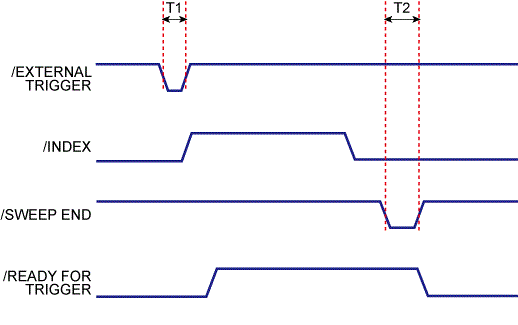
Indicates that the instrument is ready for triggering. This signal is changed to the Low level when the instrument is ready for receiving a trigger signal. With the point trigger function on, it goes to the Low level when the instrument is ready to accept the trigger signal for the first point and goes to the High level when the trigger signal for the first point is received. When measurement of all measurement points is completed and the instrument is ready to receive the trigger signal for the first point of the next sweep, this signal goes to the Low level again. |
|
Trig |
/EXTERNAL TRIGGER |
Input |
An external trigger signal. When the trigger source is set to the "External," this port generates a trigger in respond to the trailing edge of a negative pulse. |
|
|
I/O2 |
/INDEX |
Output |
Indicates that analog measurement is complete. The /INDEX signal changes to the Low level when analog measurement (all sweeps of all channels) is complete. When the handler receives the signal, it assumes that it is ready to connect the next DUT. However, no measurement data are available until data calculation is completed. When the point trigger function is on, it goes to the High level before staring measurement of the first measurement point and returns to the Low level after completing measurement of all measurement points. |
|
|
Port 2
|
I/O1 |
/SWEEP END |
Output |
A sweep completion signal. When measurement (all sweeps of all channels) and data calculation are completed, this signal provides a negative pulse. |
|
Trig |
INPUT1 |
Input |
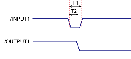
When this port receives a negative pulse, /OUTPUT1 are changed to the Low/High level depending on the setup. |
|
|
I/O2 |
OUTPUT1 |
Output |
Changes to the logic level when /INPUT1 receives a negative pulse. A command can be available for altering the Low/High level logic. |
|
|
Port 3 |
I/O1 |
P1 |
Output |
Hardwired pulse train output #1 (TTL) |
|
Trig |
PULSE SYNC IN |
Input |
Pulse generator synchronization trigger input (TTL) |
|
|
I/O2 |
P2 |
Output |
Hardwired pulse train output #2 (TTL) |
|
|
Port 4 |
I/O1 |
P3 |
Output |
Hardwired pulse train output #3 (TTL) |
|
Trig |
N/A |
N/A |
At default, no signal is assigned to Trig on Port 4 |
|
|
I/O2 |
P4 |
Output |
Hardwired pulse train output #4 (TTL) |
The user can modify the pin assignments of digital I/O port except for the three signals; READY_FOR_TRIGGER, EXTERNAL_TRIGGER and INDEX which are assigned on the PORT1. If you have two port system, it is necessary to modify this file in order to use the signals of P1 to P4 and PULSE SYNC IN.
Save the definition file according to the following examples. The VNA firmware first initializes the pin assignments to the default condition defined above then read the user defined file.
C:\\Users\Public\Public Documents\Network Analyzer\m9485a_digitalio.csv
<port number>, <signal for I/O1>, <signal for Trig>, <signal for I/O2>
|
Parameter |
Value |
|
<port number> |
2 – maximum port number in the 1st chassis |
|
<signal for I/O1> |
SWEEP_END, OUTPUT1, P1, P2, P3 or P4 |
|
<signal for Trig> |
INPUT1 or PULSE_SYNC_IN |
|
<signal for I/O2> |
SWEEP_END, OUTPUT1, P1, P2, P3 or P4 |
INPUT1 and OUTPUT1 must be assigned to the same port number
If the same signal is assigned to some of the different I/O ports, the lower port is selected. And if the same signal is assigned to the both of the I/O1 and I/O2 on the same port, the I/O1 is selected.
2 ports system with P1, PULSE SYNC IN, P2
(SWEEP_END, INPUT1, OUTPUT1, P3 and P4 are not used)
|
|
PORT1 |
PORT2 |
|
I/O 1 |
READY FOR TRIGGER |
P1 |
|
Trig |
EXTERNAL TRIGGER |
PULSE SYNC IN |
|
I/O 2 |
INDEX |
P2 |
2, P1,PULSE_SYNC_IN,P2
2 ports system with SWEEP_END, PULSE SYNC IN, P1
( INPUT1, OUTPUT1, P2 to P4 are not used)
|
|
PORT1 |
PORT2 |
|
I/O 1 |
READY FOR TRIGGER |
SWEEP_END |
|
Trig |
EXTERNAL TRIGGER |
PULSE SYNC IN |
|
I/O 2 |
INDEX |
P1 |
2, SWEEP_END,PULSE_SYNC_IN,P1
4 ports system, signal locations are assigned differently from default as shown below.
|
|
PORT1 |
PORT2 |
PORT3 |
PORT4 |
|
I/O 1 |
READY FOR TRIGGER |
SWEEP_END |
OUTPUT1 |
P4 |
|
Trig |
EXTERNAL TRIGGER |
N/A |
INPUT1 |
PULSE SYNC IN |
|
I/O 2 |
INDEX |
P1 |
P2 |
P3 |
2, SWEEP_END,,P1
3, OUTPUT1,INPUT1,P2
4, P4,PULSE SYNC IN,P3
In case of the multi-chassis configuration and M9377A is used as the 1st port receiver, the I/O2 pin must be used as Sync pin to synchronize over the chassis. Then the INDEX signal cannot be output from the I/O2 of PORT1. In this special case the INDEX signal is output from the I/O1 pin of the 1st port receiver in the 2nd chassis.
Restriction of the P1 to P4 and PULSE SYNC IN
In case of the multi-chassis configuration, the P1 to P4 can be assigned to the receivers installed in the 1st chassis. The PULSE SYNC IN can be assigned to the receivers installed in the slots which belong to the same trigger bus segment of the 1st port receiver. In standard configuration, both receiver should be in slots No. 7 to 12 for M9018A. Refer to M9018A users guide for the trigger bus segment.
Input1When this Input line receives a Low pulse from the material handler, data is latched on the OUTPUT1 lines. |
|
|
The Input Line activity can be read: |
|
|
SCPI |
|
Output1The current state of these latched TTL outputs may be set High or Low (Default setting) using the (non-user) OUTPUT commands. The next state (following a negative edge on the INPUT1 line) may be pre-loaded to High or Low (Default setting) using the user commands. For example, on the next negative pulse on the INPUT1 line, you want the OUTPUT1 line to go from 0 to 1. To do this: CONT:HAND:OUTP1:DATA 0 'Force the OUTPUT1 line to 0 |
||
|
|
SCPI |
|
|
Write User Data |
||
|
Read last value written |
||
|
Write non-user data |
||
|
Read last value written |
||
External TriggerWhen trigger source is set to external, this Input line accepts a trigger signal from the material handler. This usually means that a part is in place and ready to be tested.
|
|
|
Description |
Minimum |
Typical |
|
T1 |
Pulse width of /EXTERNAL TRIGGER |
0.1 µs |
|
|
T2 |
Pulse width of /SWEEP END |
|
10 µs |

|
|
Description |
Minimum |
Typical |
|
T1 |
Pulse width of /INPUT1 |
0.1 µs |
|
|
T2 |
Response time of /OUTPUT1 |
|
0.1 µs |

Last modified:
|
18-May-2016 |
New topic |